Toradex Verdin iMX8M Plus SoM
Overview
The Verdin iMX8M Plus is a Computer on Module (CoM) developed by Toradex. It is based on the NXP® i.MX 8M Plus family of processors (or System on Chips - SoCs).
The Verdin iMX8M Plus family consists of:
CoM |
SoC |
|---|---|
Verdin iMX8M Plus Quad 8GB Wi-Fi / Bluetooth IT |
i.MX 8M Plus Quad |
Verdin iMX8M Plus Quad 4GB Wi-Fi / Bluetooth IT |
i.MX 8M Plus Quad |
Verdin iMX8M Plus Quad 4GB IT |
i.MX 8M Plus Quad |
Verdin iMX8M Plus Quad 2GB Wi-Fi / Bluetooth IT |
i.MX 8M Plus Quad |
Verdin iMX8M Plus QuadLite 1GB IT |
i.MX 8M Plus QuadLite |
Quoting NXP:
The i.MX 8M Plus family focuses on machine learning and vision, advanced multimedia, and industrial automation with high reliability. It is built to meet the needs of Smart Home, Building, City and Industry 4.0 applications.
The Verdin iMX8M Plus integrates a total of 4 Arm Cortex™-A53 CPUs, operating at 1.6 GHz, alongside a single Arm Cortex™-M7F microcontroller operating at 800 MHz.
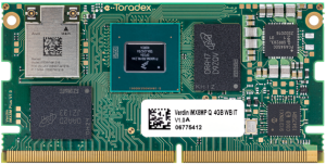
Toradex Verdin iMX8M Plus (Credit: Toradex)
Regarding the Cortex-A53 cluster, it employs the ARMv8-A architecture as a mid-range and energy-efficient processor. With four cores in this cluster, each core is equipped with its own L1 memory system. Moreover, the cluster incorporates a unified L2 cache that offers supplementary functions. This cache is housed within a single APR region. Facilitating debugging processes, the cores support both real-time trace through the ETM system and static debugging via JTAG. Furthermore, the platform features support for real-time trace capabilities, achieved through ARM’s CoreSight ETM modules, and also enables cross-triggering by utilizing CTI and CTM modules.
The Arm® Cortex®-M7 microcontroller is indicated for Real-time control, combining high-performance with a minimal interrupt latency. It stands out for its compatibility with existing Cortex-M profile processors. The microcontroller employs an efficient in-order super-scalar pipeline, allowing dual-issued instructions such as load/load and load/store pairs, thanks to its multiple memory interfaces. These interfaces encompass Tightly-Coupled Memory (TCM), Harvard caches, and an AXI master interface. The Arm Cortex-M7 Platform boasts features like a 32 KB L1 Instruction Cache, 32 KB L1 Data Cache, Floating Point Unit (FPU) with FPv5 architecture support, and an Internal Trace (TRC) mechanism. Furthermore, the chip supports 160 IRQs, and integrates crucial Arm CoreSight components including ETM and CTI, dedicated to facilitating debug and trace functions.
Hardware
SoC name: NXP® i.MX 8M Plus
CPU Type: 4x Arm Cortex™-A53 (1.6 GHz)
Microcontroller: 1x Arm Cortex™-M7F (800 MHz)
Memory:
RAM -> A53: 1GB, 2GB, 4GB or 8GB
RAM -> M7: 3x32KB (TCML, TCMU, OCRAM_S), 1x128KB (OCRAM) and 1x256MB (DDR)
Flash -> A53: Up to 32GB eMMC
Connectivity:
USB 3.1: 1x Host / 1x OTG (Gen 1)
USB 2.0: 1x Host / 1x OTG
Ethernet Gigabit with TSN (+2nd RGMII)
Wi-Fi Dual-band 802.11ac 2x2 MU-MIMO
Bluetooth 5
5x I2C
3x SPI
1 QSPI
4x UART
Up to 92 GPIO
4x Analog Input
2x CAN (FlexCAN)
Multimedia:
Neural Processing Unit (NPU)
Image Signal Processor (ISP)
2D and 3D acceleration
HDMI, MIPI-DSI and MIPI-CSI interface
For more information about the Verdin iMX8M Plus and the i.MX 8M Plus SoC refer to these links:
Supported Features
The Zephyr verdin_imx8mp_m7 board configuration supports the following hardware features:
Interface |
Controller |
Driver/Component |
|---|---|---|
NVIC |
on-chip |
nested vector interrupt controller |
SYSTICK |
on-chip |
systick |
CLOCK |
on-chip |
clock_control |
PINMUX |
on-chip |
pinmux |
UART |
on-chip |
serial port-polling; serial port-interrupt |
GPIO |
on-chip |
GPIO output GPIO input |
The default configuration can be found in the defconfig file:
boards/arm/verdin_imx8mp_m7/verdin_imx8mp_m7_itcm_defconfig, if you choose to use the ITCM memory.
boards/arm/verdin_imx8mp_m7/verdin_imx8mp_m7_ddr_defconfig, if you choose to use the DDR memory.
It is recommended to disable peripherals used by the M7 core on the Linux host.
Other hardware features are not currently supported by the port.
Connections and IOs
UART
Zephyr is configured to use the UART4 by default, which is connected to the FTDI USB converter on most Toradex carrier boards.
This is also the UART connected to WiFi/BT chip in modules that have the WiFi/BT chip. Therefore, if UART4 is used, WiFI/BT will not work properly.
If the WiFi/BT is needed, then another UART should be used for Zephyr (UART1 for example). You can
change the UART by changing the zephyr,console and zephyr,shell-uart in the
boards/arm/verdin_imx8mp_m7_itcm.dts or
boards/arm/verdin_imx8mp_m7_ddr.dts file.
Board Name |
SoC Name |
Usage |
|---|---|---|
UART_1 |
UART1 |
General purpose UART |
UART_4 |
UART4 |
Cortex-M4 debug UART |
GPIO
All the GPIO banks available are enabled in the dts/arm/nxp/nxp_imx8ml_m7.dtsi.
System Clock
The M7 Core is configured to run at a 800 MHz clock speed.
Serial Port
The i.MX8M Plus SoC has four UARTs. UART_4 is configured for the console and the remaining are not used/tested.
Programming and Debugging
The Verdin iMX8M Plus board doesn’t have QSPI flash for the M7, and it needs to be started by the A53 core. The A53 core is responsible to load the M7 binary application into the RAM, put the M7 in reset, set the M7 Program Counter and Stack Pointer, and get the M7 out of reset. The A53 can perform these steps at bootloader level or after the Linux system has booted.
The M7 can use up to 3 different RAMs (currently, only two configurations are supported: ITCM and DDR). These are the memory mapping for A53 and M7:
Region |
Cortex-A53 |
Cortex-M7 (System Bus) |
Cortex-M7 (Code Bus) |
Size |
|---|---|---|---|---|
OCRAM |
0x00900000-0x0098FFFF |
0x20200000-0x2028FFFF |
0x00900000-0x0098FFFF |
576KB |
DTCM |
0x00800000-0x0081FFFF |
0x20000000-0x2001FFFF |
128KB |
|
ITCM |
0x007E0000-0x007FFFFF |
0x00000000-0x0001FFFF |
128KB |
|
OCRAM_S |
0x00180000-0x00188FFF |
0x20180000-0x20188FFF |
0x00180000-0x00188FFF |
36KB |
DDR |
0x80000000-0x803FFFFF |
0x80200000-0x803FFFFF |
0x80000000-0x801FFFFF |
2MB |
For more information about memory mapping see the i.MX 8M Plus Applications Processor Reference Manual (section 2.1 to 2.3)
At compilation time you have to choose which RAM will be used. To facilitate this process, there are two targets available:
verdin_imx8mp_m7_itcm, which uses the ITCM configuration.verdin_imx8mp_m7_ddr, which uses the DDR configuration.
Starting the Cortex-M7 via U-Boot
Load and run Zephyr on M7 from A53 using u-boot by copying the compiled zephyr.bin to the first
FAT partition of the SD card and plug the SD card into the board. Power it up and stop the u-boot
execution at prompt.
Load the M7 binary onto the desired memory and start its execution using:
ITCM
Loading the binary from an EXT4 partition:
ext4load mmc 2:2 ${loadaddr} /<path-to-binary>/zephyr.bin
cp.b ${loadaddr} 0x7e0000 <size_of_binary_in_bytes>
bootaux 0x7e0000
DDR
Loading the binary from an EXT4 partition:
ext4load mmc 2:2 ${loadaddr} /<path-to-binary>/zephyr.bin
cp.b ${loadaddr} 0x80000000 <size_of_binary_in_bytes>
bootaux 0x80000000
Debugging
Toradex Verdin iMX8M Plus SoM can be debugged by connecting an external JLink JTAG debugger to the X56 debug connector and to the PC, or simply connecting a USB-C to X66 on the Verdin Development Board. Then, the application can be debugged using the usual way.
Here is an example for the Hello World application.
# From the root of the zephyr repository
west build -b verdin_imx8mp_m7_ddr samples/hello_world
west debug
Open a serial terminal, step through the application in your debugger, and you should see the following message in the terminal:
*** Booting Zephyr OS build zephyr-v3.4.0-2300-g03905f7e55d2  ***
Hello World! verdin_imx8mp_m7_ddr