PhyBOARD Pollux (NXP i.MX8M Plus)
Overview
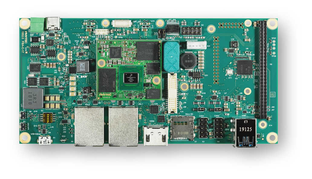
The PhyBOARD Pollux is based upon the PhyCore-i.MX8M Plus SOM which is based on the NXP i.MX8M Plus SoC. The SoC includes four Coretex-A53 cores and one Coretex-M7 core for real time applications like Zephyr. The PhyBOARD Pollux can be used for various applications like SmartHomes, Industry 4.0, IoT etc. It features a lots of interfaces and computing capacity. It can be used as a reference, to develop or in the final product too.
Board features:
Memory:
RAM: 256MB - 8GB LPDDR4
EEPROM: 4kB - 32kB
eMMC: 4GB - 64GB (eMMC 5.1)
SPI NOR Flash: 4MB - 256MB
Interfaces:
Ethernet: 2x 10/100/1000BASE-T (1x TSN Support)
USB: 2x 3.0 Host
Serial: 1x RS232 / RS485 Full Duplex / Half Duplex
CAN: 2x CAN FD
Digital I/O: via Expansion Connector
PCIe: 1x miniPCIe
MMX/SD/SDIO: microSD slot
Display: LVDS(1x4 or 1x8), MIPI DSI(1x4), HDMI
Audio: SAI
Camera: 2x MIPI CSI-2 (PhyCAM-M)
Expansion Bus: I2C, SPI, SDIO, UART, USB
JTAG: via PEB-EVAL-01
LEDs:
1x Multicolor Status LED via I2C
More information about the board can be found at the PHYTEC website.
Supported Features
The Zephyr mimx8mp_phyboard_polis board configuration supports the following hardware features:
Interface |
Controller |
Driver/Component |
|---|---|---|
NVIC |
on-chip |
nested vector interrupt controller |
SYSTICK |
on-chip |
systick |
CLOCK |
on-chip |
clock_control |
PINMUX |
on-chip |
pinmux |
UART |
on-chip |
serial port-polling; serial port-interrupt |
GPIO |
on-chip |
GPIO output GPIO input |
The default configuration can be found in the defconfig file: boards/arm/mimx8mp_phyboard_pollux/mimx8mp_phyboard_pollux_defconfig.
It’s recommended to disable peripherals used by the M7-Core on the host running on the Linux host.
Other hardware features are not currently supported with Zephyr on the M7-Core.
Connections and IOs
The following Compontens are tested and working correctly.
UART
Board Name |
SoM Name |
Usage |
|---|---|---|
Debug USB(A53) |
UART1 |
UART Debug Console via USB |
Wo WiFi Module |
UART3 |
UART to WiFi/BLE Module |
Debug USB(M4) |
UART4 |
UART Debug Console via USB |
Note
Please note, that the, to UART3 connected, Wifi/BLE Module isn’t working with Zephyr yet. UART3 can also be used through pin 31(RX) and 33(TX) of the X6 Connector.
GPIO
The pinmuxing for the GPIOs is the standard pinmuxing of the mimx8mp devicetree created by NXP. You can find it here:
dts/arm/nxp/nxp_imx8ml_m7.dtsi.
The Pinout of the PhyBOARD Polis can be found here:
Programming and Debugging
The i.MX8MP does not have a separate flash for the M7-Core. Because of this the A53-Core has to load the program for the M7-Core to the right memory address, set the PC and start the processor. This can only by done with u-boot at the moment. We are working on our BSP to enable remoteproc support.
The M7 can use up to 3 different RAMs (currently, only two configurations are supported: ITCM and DDR). These are the memory mapping for A53 and M7:
Region |
Cortex-A53 |
Cortex-M7 (System Bus) |
Cortex-M7 (Code Bus) |
Size |
|---|---|---|---|---|
OCRAM |
0x00900000-0x0098FFFF |
0x20200000-0x2028FFFF |
0x00900000-0x0098FFFF |
576KB |
DTCM |
0x00800000-0x0081FFFF |
0x20000000-0x2001FFFF |
128KB |
|
ITCM |
0x007E0000-0x007FFFFF |
0x00000000-0x0001FFFF |
128KB |
|
OCRAM_S |
0x00180000-0x00188FFF |
0x20180000-0x20188FFF |
0x00180000-0x00188FFF |
36KB |
DDR |
0x80000000-0x803FFFFF |
0x80200000-0x803FFFFF |
0x80000000-0x801FFFFF |
2MB |
For more information about memory mapping see the i.MX 8M Plus Applications Processor Reference Manual (section 2.1 to 2.3)
At compilation time you have to choose which memory region will be used. This configuration is done in the devicetree and the defconfig / the config of your program.
By default Zephyr will use the TCM memory region. You can configure it like this for the DDR region:
In the devicetree overwrite the following nodes like this:
chosen {
   /* TCM */
   zephyr,flash = &itcm;
        zephyr,sram = &dtcm;
};
change it to
chosen {
   /* DDR */
   zephyr,flash = &ddr_code;
   zephyr,sram = &ddr_sys;
};
In your prj.conf overwrite the configuration like this for the DDR memory region:
CONFIG_CODE_DDR=y
CONFIG_CODE_ITCM=n
Starting the M7-Core via U-Boot
Load the compiled zephyr.bin to memory address 0x4800000. This should output something like this:
u-boot=> tftp 0x48000000 192.168.3.10:zyphr.bin
Using ethernet@30be0000 device
TFTP from server 192.168.3.10; our IP address is 192.168.3.11
Filename 'zepyhr.bin'.
Load address: 0x48000000
Loading: ##
         2 KiB/s
done
Bytes transferred = 27240 (6a68 hex)
Because it’s not possible to load directly to the TCM memory area you have to copy the binaries. The last argument given is the size of the file in bytes, you can copy it from the output of the last command.
u-boot=> cp.b 0x48000000 0x7e0000 27240
And finaly starting the M7-Core at the right memory address:
u-boot=> bootaux 0x7e0000
## Starting auxiliary core stack = 0x20003A58, pc = 0x1FFE1905...
Debugging
The PhyBOARD Polis can be debugged using a JTAG Debugger.
The easiest way to do that is to use a SEGGER JLink Debugger and Phytec’s
PEB-EVAL-01 Shield, which can be directly connected to the JLink.
You can find the JLink Software package here: JLink Software
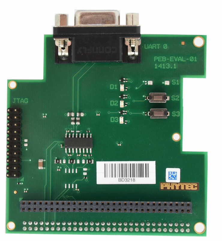
PEB-EVAL-01
To debug efficiently you have to use multiple terminals:
After connecting everything and building with west use this command while in the directory of the program you build earlier to start a debug server:
host$ west debugserver
West automatically connects via the JLink to the Target and keeps open a debug server.
Use another terminal, start gdb, connect to target and load Zephyr on the target:
host$ gdb-multiarch build/zephyr/zephyr.elf -tui
(gdb) targ rem :2331
Remote debugging using :2331
0x1ffe0008 in _vector_table ()
(gdb) mon halt
(gdb) mon reset
(gdb) c
Continuing.
The program can be debugged using standard gdb techniques.