Digilent Arty
Overview
The Digilent Arty is a line of FPGA-based development boards aimed for makers and hobbyists. The Arty is available in several configurations, each with a different Xilinx FPGA (Spartan-7, Artix-7, or Zynq-7000 series).
Each board is equipped with on-board JTAG for FPGA programming and debugging, LEDs, switches, buttons, DDR3 RAM, and QSPI flash for storing the FPGA bitstream.
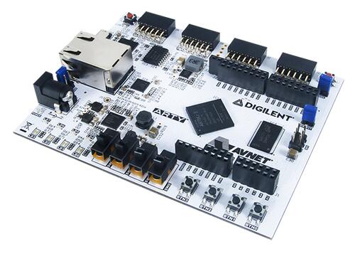
Digilent Arty A7-35 (Credit: Digilent Inc)
The Spartan-7 and Artix-7 based Arty board do not contain a CPU, but require a so-called soft processor to be instantiated within the FPGA in order to run Zephyr. The Zynq-7000 based Arty boards are not yet supported by Zephyr.
ARM Cortex-M1/M3 DesignStart FPGA
One way of instantiating soft processors on the Arty is using the ARM DesignStart FPGA Xilinx edition reference designs from ARM. Zephyr supports both the Cortex-M1 and the Cortex-M3 reference designs. The Cortex-M1 design targets either the Spartan-7 or Artix-7 based Arty boards, whereas the Cortex-M3 design only targets the Artix-7 based boards. Zephyr only supports the Artix-7 targeted designs for now.
For more information about the ARM Cortex-M1/M3 DesignStart FPGA, see the following websites:
Supported Features
The arty_a7_arm_designstart_m1 board configuration supports the following
hardware features of the Cortex-M1 reference design:
Interface |
Controller |
Driver/Component |
|---|---|---|
NVIC |
on-chip |
nested vector interrupt controller |
SYSTICK |
on-chip |
systick |
GPIO |
on-chip |
gpio, non-interrupt |
UART |
on-chip |
serial port-polling; serial port-interrupt |
QSPI |
on-chip |
QSPI flash |
The default configuration for the Cortex-M1 can be found in the defconfig file:
boards/arm/arty/arty_a7_arm_designstart_m1_defconfig.
In addition to the above, the arty_a7_arm_designstart_m3 board configuration
supports the following hardware features of the Cortex-M3 reference design:
Interface |
Controller |
Driver/Component |
|---|---|---|
MPU |
on-chip |
Memory Protection Unit |
The default configuration for the Cortex-M3 can be found in the defconfig file:
boards/arm/arty/arty_a7_arm_designstart_m3_defconfig.
Other hardware features are not currently supported by the port.
System Clock
The Cortex-M1 reference design is configured to use the 100 MHz external oscillator on the board as CPU system clock whereas the Cortex-M3 reference design is configured for 50MHz CPU system clock.
Serial Port
The reference design contains one Xilinx UART Lite. This UART is configured as
console and is accessible through the on-board JTAG adapter via USB connector
J10.
Connecting the Debug Probes
Two different debug probes are needed in order to program the board; the on-board Digilent JTAG connected to the FPGA, and an external Serial Wire Debug (SWD) capable debug probe connected to the ARM Cortex-M1 CPU.
The on-board JTAG is used for configuring and debugging the Xilinx FPGA
itself. It is available on USB connector J10.
The external SWD debug probe can be connected to connector J4 (nSRST on
IO39, SWDIO on IO40, and SWCLK on IO41). Another option is
to use the dedicated ARM V2C-DAPLink for DesignStart FPGA.
Programming and Debugging
First, configure the FPGA with the selected reference design FPGA bitstream using Xilinx Vivado as described in the ARM Cortex-M1/Cortex-M3 DesignStart FPGA Xilinx edition user guide (available as part of the reference design download from Technical Resources for DesignStart FPGA on Xilinx).
Another option for configuring the FPGA with the reference design bitstream is to use the OpenOCD Debug Host Tools:
openocd -f board/arty_s7.cfg -c "init;\
     pld load 0 m1_for_arty_a7_reference.bit;\
     shutdown"
or:
openocd -f board/arty_s7.cfg -c "init;\
     pld load 0 m3_for_arty_a7_reference.bit;\
     shutdown"
Note
The pre-built FPGA bitstream only works for Arty boards equipped with an Artix-35T FPGA. For other Arty variants (e.g. the Arty A7-100) the bitstream must be rebuilt.
Next, build and flash applications as usual (see Building an Application and Run an Application for more details).
Configuring a Console
The UART console is available via the on-board JTAG on USB connector
J10. The on-board JTAG will enumerate as two USB serial ports. The UART is
typically available on the second serial port.
Use the following settings with your serial terminal of choice (minicom, putty, etc.):
Speed: 115200
Data: 8 bits
Parity: None
Stop bits: 1
Flashing
Here is an example for building and flashing the Hello World application for the Cortex-M1 reference design:
# From the root of the zephyr repository
west build -b arty_a7_arm_designstart_m1 samples/hello_world
west flash
After flashing, you should see message similar to the following in the terminal:
*** Booting Zephyr OS build zephyr-v2.3.99  ***
Hello World! arty_a7_arm_designstart_m1
The same procedure can be used for the Cortex-M3 reference design.
Note, however, that the application was not persisted in flash memory by the above steps. It was merely written to internal block RAM in the FPGA. It will revert to the application stored in the block RAM within the FPGA bitstream the next time the FPGA is configured.
The steps to persist the application within the FPGA bitstream are covered by
the ARM Cortex-M1/M3 DesignStart FPGA Xilinx edition user guide. If the
CONFIG_BUILD_OUTPUT_BIN is enabled and the SiFive elf2hex package
is available, the build system will automatically generate a Verilog memory hex
dump zephyr.mem file suitable for initialising the block RAM using
Xilinx Vivado.
Debugging
Here is an example for the Hello World application.
# From the root of the zephyr repository
west build -b arty_a7_arm_designstart_m1 samples/hello_world
west debug
Step through the application in your debugger, and you should see a message similar to the following in the terminal:
*** Booting Zephyr OS build zephyr-v2.3.99  ***
Hello World! arty_a7_arm_designstart_m1