ST STM32G081B Evaluation
Overview
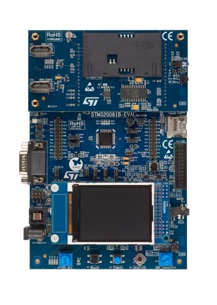
The STM32G081B-EVAL Evaluation board is a high-end development platform, for Arm Cortex-M0+ core-based STM32G081RBT6 microcontroller, with USB Type-C and power delivery controller interfaces (UCPD), compliant with USB type-C r1.2 and USB PD specification r3.0, two I2Cs, two SPIs, five USARTs, one LP UART, one 12-bit ADC, two 12-bit DACs, two GP comparators, two LP timers, internal 32 KB SRAM and 128 KB Flash, CEC, SWD debugging support. The full range of hardware features on the STM32G081B-EVAL Evaluation board includes a mother board, a legacy peripheral daughterboard and a USB-C and Power Delivery daughterboard, which help to evaluate all peripherals (USB Type-C connector with USB PD, motor control connector, RS232, RS485, Audio DAC, microphone ADC, TFT LCD, IrDA, IR LED, IR receiver, LDR, MicroSD card, CEC on two HDMI connectors, smart card slot, RF E2PROM & Temperature sensor…), and to develop applications.
The board integrates an ST-LINK/V2-1 as an embedded in-circuit debugger and programmer for the STM32 MCU. The daughterboard and extension connectors provide an easy way to connect a daughterboard or wrapping board for the user’s specific applications.
The USB-C and Power Delivery daughterboard features two independent USB-C ports controlled by an STM32G0. USB-C port 1 is dual role power (DRP) and can provide up-to 45 W. USB-C Port 2 is sink only. Both support USB PD protocol and alternate mode functionality.
Application firmware examples are provided to evaluate the USB-C technology through various use cases.
- Mother board
STM32G081RBT6 microcontroller with 128 Kbytes of Flash memory and 32 Kbytes of RAM in LQFP64 package
MCU voltage choice fixed 3.3 V or adjustable from 1.65 V to 3.6 V
I2C compatible serial interface
RTC with backup battery
8-Gbyte or more SPI interface microSD card
Potentiometer
4 color user LEDs and one LED as MCU low-power alarm
Reset, Tamper and User buttons
4-direction control and selection joystick
- Board connectors:
5 V power jack
RS-232 and RS485 communications
Stereo audio jack including analog microphone input
microSD card
Extension I2C connector
Motor-control connector
- Board extension connectors:
Daughterboard connectors for legacy peripheral daughter board or USB-C daughterboard
Extension connectors for daughterboard or wire-wrap board
- Flexible power-supply options:
5 V power jack
ST-LINK/V2-1 USB connector
Daughterboard
On-board ST-LINK/V2-1 debugger/programmer with USB re-enumeration capability: mass storage, virtual COM port and debug port
- Legacy peripheral daughterboard
IrDA transceiver
IR LED and IR receiver
Light dependent resistor (LDR)
Temperature Sensor
- Board connectors:
Two HDMI connectors with DDC and CEC
Smart card slot
- USB-C and Power Delivery daughterboard
Mux for USB3.1 Gen1 / DisplayPort input and Type-C port1 output
Mux for Type-C port2 input and DisplayPort output / USB2.0
VCONN on Type-C port1
USB PD on Type-C port1
- Board connectors:
Type-C port1 DRP (dual-role port)
Type-C port2 Sink
DisplayPort input
DisplayPort output
USB 3.1 Gen1 Type-B receptacle
USB2.0 Type-A receptacle
19 V power jack for USB PD
More information about the board can be found at the STM32G081B-EVAL website [1].
More information about STM32G081RB can be found here: - G081RB on www.st.com [4] - STM32G081 reference manual [2]
Supported Features
The Zephyr stm32g081b_eval board configuration supports the following hardware features:
Interface |
Controller |
Driver/Component |
|---|---|---|
NVIC |
on-chip |
nested vector interrupt controller |
UART |
on-chip |
serial port-polling; serial port-interrupt |
UCPD |
on-chip |
ucpd |
ADC |
on-chip |
adc |
GPIO |
on-chip |
gpio |
WATCHDOG |
on-chip |
independent watchdog |
Other hardware features are not yet supported in this Zephyr port.
The default configuration can be found in the defconfig file:
boards/arm/stm32g081b_eval/stm32g081b_eval_defconfig
Connections and IOs
Each of the GPIO pins can be configured by software as output (push-pull or open-drain), as input (with or without pull-up or pull-down), or as peripheral alternate function. Most of the GPIO pins are shared with digital or analog alternate functions. All GPIOs are high current capable except for analog inputs.
Default Zephyr Peripheral Mapping:
UART_3 TX/RX : PC10/PC11 (ST-Link Virtual Port Com)
UCPD2 : PD0/PD2
BUTTON (JOY_SEL) : PA0
BUTTON (JOY_LEFT) : PC8
BUTTON (JOY_DOWN) : PC3
BUTTON (JOY_RIGHT) : PC7
BUTTON (JOY_UP) : PC2
VBUS DISCHARGE : PB14
LED1 : PD5
LED2 : PD6
LED3 : PD8
LED4 : PD9
For more details please refer to STM32G0 Evaluation board User Manual [3].
Programming and Debugging
Applications for the stm32g081b_eval board configuration can be built and
flashed in the usual way (see Building an Application and
Run an Application for more details).
Flashing
The STM32G081B Evaluation board includes an ST-LINK/V2-1 embedded debug tool interface.
$ west flash
Flashing an application to the STM32G081B_EVAL
Here is an example for the Blinky application.
# From the root of the zephyr repository
west build -b stm32g081b_eval samples/basic/blinky
west flash
You will see the LED blinking every second.
Debugging
You can debug an application in the usual way. Here is an example for the Hello World application.
# From the root of the zephyr repository
west build -b stm32g081b_eval samples/hello_world
west debug