PJRC TEENSY 4
Overview
The Teensy is a complete USB-based microcontroller development system, in a very small footprint, capable of implementing many types of projects. All programming is done via the USB port.
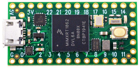
TEENSY40 (Credit: https://www.pjrc.com)
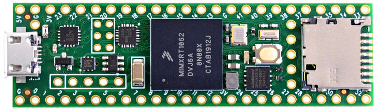
TEENSY41 (Credit: https://www.pjrc.com)
Hardware
Teensy 4.0:
MIMXRT1062DVL6A MCU (600 MHz, 1024 KB on-chip memory)
16 Mbit QSPI Flash
LED
USB 2.0 host connector
Teensy 4.1:
MIMXRT1062DVJ6A MCU (600 MHz, 1024 KB on-chip memory)
64 Mbit QSPI Flash
LED
USB 2.0 host connector
USB 2.0 OTG connector
10/100 Mbit/s Ethernet PHY
TF socket for SD card
See the Teensy 4.0 Website for a complete hardware description.
Supported Features
The teensy40 board configuration supports the following hardware features:
Interface |
Controller |
Driver/Component |
|---|---|---|
NVIC |
on-chip |
nested vector interrupt controller |
SYSTICK |
on-chip |
systick |
GPIO |
on-chip |
gpio |
I2C |
on-chip |
i2c |
UART |
on-chip |
serial port-polling; serial port-interrupt |
USB |
on-chip |
USB device |
The default configuration can be found in the defconfig file:
boards/arm/teensy4/teensy40_defconfig
The teensy41 board configuration supports additional hardware features:
Interface |
Controller |
Driver/Component |
|---|---|---|
SDHC |
on-chip |
disk access |
ENET |
on-chip |
ethernet |
The default configuration can be found in the defconfig file:
boards/arm/teensy4/teensy41_defconfig
Other hardware features are not currently supported by the port.
Connections and IOs
Pin mappings from Teensy to MIMXRT1062 SoC.
Pin |
Pad ID |
Usage |
|---|---|---|
0 |
AD_B0_03 |
GPIO1_3 / UART6_RX / CAN2_RX |
1 |
AD_B0_02 |
GPIO1_2 / UART6_TX / CAN2_TX |
2 |
EMC_04 |
GPIO4_4 |
3 |
EMC_05 |
GPIO4_5 |
4 |
EMC_06 |
GPIO4_6 |
5 |
EMC_08 |
GPIO4_8 |
6 |
B0_10 |
GPIO2_10 |
7 |
B1_01 |
GPIO2_17 / UART4_RX |
8 |
B1_00 |
GPIO2_16 / UART4_TX |
9 |
B0_11 |
GPIO2_11 |
10 |
B0_00 |
GPIO2_0 |
11 |
B0_02 |
GPIO2_2 |
12 |
B0_01 |
GPIO2_1 |
13 |
B0_03 |
GPIO2_3 / LED |
14 |
AD_B1_02 |
GPIO1_18 / UART2_TX |
15 |
AD_B1_03 |
GPIO1_19 / UART2_RX |
16 |
AD_B1_07 |
GPIO1_23 / UART3_RX / I2C3_SCL |
17 |
AD_B1_06 |
GPIO1_22 / UART3_TX / I2C3_SDA |
18 |
AD_B1_01 |
GPIO1_17 / I2C1_SDA |
19 |
AD_B1_00 |
GPIO1_16 / I2C1_SCL |
20 |
AD_B1_10 |
GPIO1_26 / UART8_TX |
21 |
AD_B1_11 |
GPIO1_27 / UART8_RX |
22 |
AD_B1_08 |
GPIO1_24 / CAN1_TX |
23 |
AD_B1_09 |
GPIO1_25 / CAN1_RX |
24 |
AD_B0_12 |
GPIO1_12 / UART1_TX / I2C4_SCL |
25 |
AD_B0_13 |
GPIO1_13 / UART1_RX / I2C4_SDA |
26 |
AD_B1_14 |
GPIO1_30 |
27 |
AD_B1_15 |
GPIO1_31 |
28 |
EMC_32 |
GPIO3_18 / UART7_RX |
29 |
EMC_31 |
GPIO4_31 / UART7_TX |
30 |
EMC_37 |
GPIO3_23 / CAN3_RX |
31 |
EMC_36 |
GPIO3_22 / CAN3_TX |
32 |
B0_12 |
GPIO2_12 |
33 |
EMC_07 |
GPIO4_7 |
Only Teensy 4.0:
34 |
SD_B0_03 |
GPIO3_15 |
35 |
SD_B0_02 |
GPIO3_14 |
36 |
SD_B0_01 |
GPIO3_13 |
37 |
SD_B0_00 |
GPIO3_12 |
38 |
SD_B0_05 |
GPIO3_17 |
39 |
SD_B0_04 |
GPIO3_16 |
Only Teensy 4.1:
34 |
B1_13 |
GPIO2_29 / UART5_RX |
35 |
B1_12 |
GPIO2_28 / UART5_TX |
36 |
B1_02 |
GPIO2_18 |
37 |
B1_03 |
GPIO2_19 |
38 |
AD_B1_12 |
GPIO1_28 |
39 |
AD_B1_13 |
GPIO1_29 |
40 |
AD_B1_04 |
GPIO1_20 |
41 |
AD_B1_05 |
GPIO1_21 |
Programming and Debugging
Flashing
Build applications as usual (see Building an Application for more details).
Flash hex-file with the documented tools:
Debugging
Console output is mapped to teensy pins 0 (RX1) and 1 (TX1). Connect a usb-to-serial adapter to use this serial console. Use the following settings with your serial terminal of choice (minicom, putty, etc.):
Speed: 115200
Data: 8 bits
Parity: None
Stop bits: 1