NXP FRDM-KL25Z
Overview
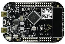
The Freedom KL25Z is an ultra-low-cost development platform for Kinetis® L Series KL1x (KL14/15) and KL2x (KL24/25) MCUs built on ARM® Cortex®-M0+ processor.
The FRDM-KL25Z features include easy access to MCU I/O, battery-ready, low-power operation, a standard-based form factor with expansion board options and a built-in debug interface for flash programming and run-control.
Hardware
MKL25Z128VLK4 MCU @ 48 MHz, 128 KB flash, 16 KB SRAM, USB OTG (FS), 80LQFP
On board capacitive touch “slider”, MMA8451Q accelerometer, and tri-color LED
OpenSDA debug interface
For more information about the KL25Z SoC and FRDM-KL25Z board:
Supported Features
The frdm_kl25z board configuration supports the following hardware features:
Interface |
Controller |
Driver/Component |
|---|---|---|
NVIC |
on-chip |
nested vector interrupt controller |
SYSTICK |
on-chip |
systick |
PINMUX |
on-chip |
pinmux |
GPIO |
on-chip |
gpio |
UART |
on-chip |
serial port-polling; serial port-interrupt |
I2C |
on-chip |
i2c |
ADC |
on-chip |
adc |
FLASH |
on-chip |
soc flash |
USB |
on-chip |
USB device |
The default configuration can be found in the defconfig file:
boards/arm/frdm_kl25z/frdm_kl25z_defconfig
Other hardware features are not currently supported by the port.
Connections and IOs
The KL25Z SoC has five pairs of pinmux/gpio controllers, and all are currently enabled (PORTA/GPIOA, PORTB/GPIOB, PORTC/GPIOC, PORTD/GPIOD, and PORTE/GPIOE) for the FRDM-KL25Z board.
Name |
Function |
Usage |
|---|---|---|
PTB2 |
ADC |
ADC0 channel 12 |
PTB18 |
GPIO |
Red LED |
PTB19 |
GPIO |
Green LED |
PTD1 |
GPIO |
Blue LED |
PTA1 |
UART0_RX |
UART Console |
PTA2 |
UART0_TX |
UART Console |
PTE24 |
I2C0_SCL |
I2C |
PTE25 |
I2C0_SDA |
I2C |
System Clock
The KL25Z SoC is configured to use the 8 MHz external oscillator on the board with the on-chip FLL to generate a 48 MHz system clock.
Serial Port
The KL25Z UART0 is used for the console.
USB
The KL25Z SoC has a USB OTG (USBOTG) controller that supports both device and host functions through its mini USB connector (USB KL25Z). Only USB device function is supported in Zephyr at the moment.
Programming and Debugging
Build and flash applications as usual (see Building an Application and Run an Application for more details).
Configuring a Debug Probe
A debug probe is used for both flashing and debugging the board. This board is configured by default to use the OpenSDA DAPLink Onboard Debug Probe.
Early versions of this board have an outdated version of the OpenSDA bootloader and require an update. Please see the DAPLink Bootloader Update page for instructions to update from the CMSIS-DAP bootloader to the DAPLink bootloader.
Option 1: Linkserver: OpenSDA DAPLink Onboard Debug Probe (Recommended)
Install the LinkServer Debug Host Tools and make sure they are in your search path. LinkServer works with the CMSIS-DAP debug firmware. Please follow the instructions on OpenSDA DAPLink Onboard Debug Probe and select the latest revision of the firmware image.
Linkserver is the default for this board,
west flashandwest debugwill call the linkserver runner.west flash west debug
Option 2: OpenSDA J-Link Onboard Debug Probe
Install the J-Link Debug Host Tools and make sure they are in your search path.
Follow the instructions in OpenSDA J-Link Onboard Debug Probe to program the OpenSDA J-Link FRDM-KL25Z Firmware.
Add the arguments -DBOARD_FLASH_RUNNER=jlink and
-DBOARD_DEBUG_RUNNER=jlink when you invoke west build to override the
default runner from pyOCD to J-Link:
# From the root of the zephyr repository
west build -b frdm_kl25z samples/hello_world -- -DBOARD_FLASH_RUNNER=jlink -DBOARD_DEBUG_RUNNER=jlink
Note:
The runners supported by NXP are LinkServer and JLink. pyOCD is another potential option, but NXP does not test or support the pyOCD runner.
Configuring a Console
Regardless of your choice in debug probe, we will use the OpenSDA microcontroller as a usb-to-serial adapter for the serial console.
Connect a USB cable from your PC to J7.
Use the following settings with your serial terminal of choice (minicom, putty, etc.):
Speed: 115200
Data: 8 bits
Parity: None
Stop bits: 1
Flashing
Here is an example for the Hello World application.
# From the root of the zephyr repository
west build -b frdm_kl25z samples/hello_world
west flash
Open a serial terminal, reset the board (press the SW1 button), and you should see the following message in the terminal:
***** Booting Zephyr OS v1.14.0-rc1 *****
Hello World! frdm_kl25z
Debugging
Here is an example for the Hello World application.
# From the root of the zephyr repository
west build -b frdm_kl25z samples/hello_world
west debug
Open a serial terminal, step through the application in your debugger, and you should see the following message in the terminal:
***** Booting Zephyr OS v1.14.0-rc1 *****
Hello World! frdm_kl25z