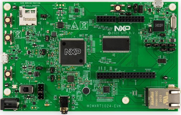
NXP MIMXRT1024-EVK
Overview
The i.MX RT1024 expands the i.MX RT crossover processor families by providing high-performance feature set in low-cost LQFP packages, further simplifying board design and layout for customers. The i.MX RT1024 runs on the Arm® Cortex®-M7 core at 500 MHz.
Hardware
MIMXRT1024DAG5A MCU (600 MHz, 256 KB on-chip memory, 4096KB on-chip QSPI flash)
Memory
256 Mbit SDRAM
32 Mbit QSPI Flash
TF socket for SD card
Connectivity
10/100 Mbit/s Ethernet PHY
Micro USB host and OTG connectors
CAN transceivers
Arduino interface
Audio
Audio Codec
4-pole audio headphone jack
Microphone
External speaker connection
Power
5 V DC jack
Debug
JTAG 10-pin connector
OpenSDA with DAPLink
Sensor
6-axis FXOS8700CQ digital accelerometer and magnetometer
For more information about the MIMXRT1024 SoC and MIMXRT1024-EVK board, see these references:
External Memory
This platform has the following external memories:
Device |
Controller |
Status |
|---|---|---|
MT48LC16M16A2P |
SEMC |
Enabled via device configuration data block, which sets up SEMC at boot time |
Supported Features
The mimxrt1024_evk board configuration supports the hardware features listed below. For additional features not yet supported, please also refer to the NXP MIMXRT1064-EVK , which is the superset board in NXP’s i.MX RT10xx family. NXP prioritizes enabling the superset board with NXP’s Full Platform Support for Zephyr. Therefore, the mimxrt1064_evk board may have additional features already supported, which can also be re-used on this mimxrt1024_evk board:
Interface |
Controller |
Driver/Component |
|---|---|---|
NVIC |
on-chip |
nested vector interrupt controller |
SYSTICK |
on-chip |
systick |
FLASH |
on-chip |
QSPI flash |
GPIO |
on-chip |
gpio |
UART |
on-chip |
serial port-polling; serial port-interrupt |
SPI |
on-chip |
spi |
ENET |
on-chip |
ethernet |
CAN |
on-chip |
can |
WATCHDOG |
on-chip |
watchdog |
HWINFO |
on-chip |
reset cause |
DMA |
on-chip |
dma |
ADC |
on-chip |
adc |
GPT |
on-chip |
gpt |
USB |
on-chip |
USB |
TRNG |
on-chip |
entropy |
FLEXSPI |
on-chip |
flash programming |
The default configuration can be found in the defconfig file:
boards/arm/mimxrt1024_evk/mimxrt1024_evk_defconfig
Other hardware features are not currently supported by the port.
Connections and I/Os
The MIMXRT1024 SoC has five pairs of pinmux/gpio controllers.
Name |
Function |
Usage |
|---|---|---|
GPIO_AD_B1_08 |
GPIO |
LED |
GPIO_AD_B0_06 |
LPUART1_TX |
UART Console |
GPIO_AD_B0_07 |
LPUART1_RX |
UART Console |
WAKEUP |
GPIO |
SW4 |
GPIO_AD_B0_04 |
ENET_RST |
Ethernet |
GPIO_AD_B0_08 |
ENET_REF_CLK |
Ethernet |
GPIO_AD_B0_09 |
ENET_RX_DATA01 |
Ethernet |
GPIO_AD_B0_10 |
ENET_RX_DATA00/LPSPI1_SCK | Ethernet/SPI |
|
GPIO_AD_B0_11 |
ENET_RX_EN/LPSPI1_PCS0 | Ethernet/SPI |
|
GPIO_AD_B0_12 |
ENET_RX_ER/LPSPI1_SDO | Ethernet/SPI |
|
GPIO_AD_B0_13 |
ENET_TX_EN/LPSPI1_SDI | Ethernet/SPI |
|
GPIO_AD_B0_14 |
ENET_TX_DATA00 |
Ethernet |
GPIO_AD_B0_15 |
ENET_TX_DATA01 |
Ethernet |
GPIO_AD_B1_06 |
ENET_INT |
Ethernet |
GPIO_EMC_41 |
ENET_MDC |
Ethernet |
GPIO_EMC_40 |
ENET_MDIO |
Ethernet |
GPIO_SD_B1_00 |
FLEXCAN1_TX |
CAN TX |
GPIO_SD_B1_01 |
FLEXCAN1_RX |
CAN RX |
GPIO_SD_B1_02 |
LPI2C4_SCL |
I2C SCL |
GPIO_SD_B1_03 |
LPI2C4_SDA |
I2C SDA |
GPIO_SD_B1_05 |
DQS |
QSPI flash |
GPIO_AD_B1_11 |
ADC1 |
ADC1 Channel 11 |
GPIO_AD_B1_10 |
ADC1 |
ADC1 Channel 10 |
GPIO_AD_B1_10 |
FLEXPWM1 |
FLEXPWM1 Channel A2 |
System Clock
The MIMXRT1024 SoC is configured to use SysTick as the system clock source, running at 500MHz.
When power management is enabled, the 32 KHz low frequency oscillator on the board will be used as a source for the GPT timer to generate a system clock. This clock enables lower power states, at the cost of reduced resolution
Serial Port
The MIMXRT1024 SoC has eight UARTs. One is configured for the console and the remaining are not used.
Programming and Debugging
Build and flash applications as usual (see Building an Application and Run an Application for more details).
Configuring a Debug Probe
A debug probe is used for both flashing and debugging the board. This board is configured by default to use the OpenSDA DAPLink Onboard Debug Probe, however the pyOCD Debug Host Tools do not yet support programming the external flashes on this board so you must reconfigure the board for one of the following debug probes instead.
J-Link External Debug Probe
Install the J-Link Debug Host Tools and make sure they are in your search path.
Attach a J-Link 10-pin connector to J55. Check that jumpers J47 and J48 are off (they are on by default when boards ship from the factory) to ensure SWD signals are disconnected from the OpenSDA microcontroller.
Configuring a Console
Regardless of your choice in debug probe, we will use the OpenSDA microcontroller as a usb-to-serial adapter for the serial console. Check that jumpers J50 and J46 are on (they are on by default when boards ship from the factory) to connect UART signals to the OpenSDA microcontroller.
Connect a USB cable from your PC to J23.
Use the following settings with your serial terminal of choice (minicom, putty, etc.):
Speed: 115200
Data: 8 bits
Parity: None
Stop bits: 1
Flashing
Here is an example for the Hello World application.
# From the root of the zephyr repository
west build -b mimxrt1024_evk samples/hello_world
west flash
Open a serial terminal, reset the board (press the SW9 button), and you should see the following message in the terminal:
***** Booting Zephyr OS v2.4.0-rc1 *****
Hello World! mimxrt1024_evk
Debugging
Here is an example for the Hello World application.
# From the root of the zephyr repository
west build -b mimxrt1024_evk samples/hello_world
west debug
Open a serial terminal, step through the application in your debugger, and you should see the following message in the terminal:
***** Booting Zephyr OS v2.4.0-rc1 *****
Hello World! mimxrt1024_evk
Experimental ENET Driver
Current default ethernet driver is eth_mcux, with binding nxp,kinetis-ethernet. There is a new driver with binding nxp,enet, which is experimental and undergoing development, but will have enhanced capability, such as not hardcoding code for only one phy in the driver like eth_mcux.
To build for this EVK with the new driver, include the experimental overlay to west build with the option -DEXTRA_DTC_OVERLAY_FILE=nxp,enet-experimental.overlay.