Adafruit Feather STM32F405 Express
Overview
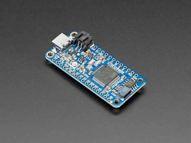
The Adafruit Feather STM32F405 is an ARM Development board in the Feather standard layout, sharing peripheral placement with other devices labeled as Feathers or FeatherWings. The board is equipped with a lithium ion battery charger, native USB C connector, 2MB of external flash memory, and SD card socket.
Hardware
STM32F405 Cortex M4 with FPU and 1MB Flash, 168MHz speed
192KB RAM total - 128 KB RAM + 64 KB program-only/cache RAM
USB C power and data
LiPo connector and charger
SD socket on the bottom, connected to SDIO port
2 MB SPI Flash chip
Built in NeoPixel indicator
I2C, UART, GPIO, ADCs, DACs
Qwiic/STEMMA-QT connector for fast I2C connectivity
SWD SMT mount region on board underside.
Supported Features
The Adafruit Feather STM32F405 board configuration supports the following hardware features:
Interface |
Controller |
Driver/Component |
|---|---|---|
NVIC |
on-chip |
nested vectored interrupt controller |
SYSTICK |
on-chip |
system clock |
UART |
on-chip |
serial port |
GPIO |
on-chip |
gpio |
I2C |
on-chip |
i2c |
SPI |
on-chip |
spi |
USB |
on-chip |
USB device |
Other hardware features have not been enabled yet for this board.
Connections and IOs
The Adafruit Feather STM32F405 Express Learn site [1] has detailed information about the board including pinouts [2] and the schematic [3].
System Clock
The STM32F405 is configured to use the 12MHz HSE Oscillator to produce a 168MHz system clock.
Serial Port
The STM32F405 UART 3 peripheral is available on the TX (PB10) and RX (PB11) pins.
I2C Port
The STM32F405 I2C1 peripheral is available on the SDA (PB7) and SCL (PB6) pins.
SPI Port
The STM32F405 SPI2 peripheral is available on the SCK (PB13), MI (PB14) and MO (PB15) pins.
SPI1 uses SCK (PB3), MI (PB4), MO (PB5) and SS (PA15) pins and is dedicated to the 2 MB SPI Flash chip.
Programming and Debugging
DFU-Util programming is supported through Zephyr by default. Set up of the built in DFU-Util bootloader is possible by following the instructions on the Learn website [4].
Flashing
Build the Zephyr kernel and the Blinky sample application:
west build -b adafruit_feather_stm32f405 samples/basic/blinky
On the Adafruit Feather STM32F405, connect the 3.3V pin to the B0 boot pin with a jumper wire.
Flash the image:
west build -b adafruit_feather_stm32f405 samples/basic/blinky
west flash
You should see the D13 LED blinking.