ST STM32L1 Discovery
Overview
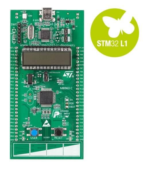
The two generations of the STM32L1 Discovery development boards come with an integrated ST-LINK/V2 debugger and programmer. The boards have a 24-segment LCD and a touch slider, along with two user LEDs and a user button. Support circuitry for measuring power consumption is also available. It also comes with a comprehensive STM32 software HAL library and various packaged software examples.
There are two variants of the board:
STM32LDISCOVERY targets STM32L152RBT6, with 128K flash, 16K RAM
32L152CDISCOVERY targets STM32L152RCT6, with 256K flash, 32K RAM
The STM32LDISCOVERY is no longer sold, but was widely available. The current configuration assumes only 128K flash and 16K RAM, so it builds and runs on both variants out of the box.
More information about the board can be found at the STM32LDISCOVERY website [1].
Hardware
The STM32 Discovery board features:
On-board ST-LINK/V2 with selection mode switch to use the kit as a standalone ST-LINK/V2 (with SWD connector for programming and debugging)
Board power supply: through USB bus or from an external 5 V supply voltage
External application power supply: 3 V and 5 V
Four LEDs:
LD1 (red) for 3.3 V power on
LD2 (red/green) for USB communication
LD3 (green) for PC9 output
LD4 (blue) for PC8 output
Two push buttons (user and reset)
Extension header for all LQFP64 I/Os for quick connection to prototyping board and easy probing
More information about STM32L151x can be found in the STM32L1x reference manual [2].
Supported Features
The Zephyr stm32l1_disco board configuration supports the following hardware features:
Interface |
Controller |
Driver/component |
|---|---|---|
NVIC |
on-chip |
nested vector interrupt controller |
UART |
on-chip |
serial port-polling serial port-interrupt |
PINMUX |
on-chip |
pinmux |
GPIO |
on-chip |
gpio |
CLOCK |
on-chip |
reset and clock control |
FLASH |
on-chip |
flash memory |
WATCHDOG |
on-chip |
window watchdog |
I2C |
on-chip |
i2c |
SPI |
on-chip |
spi |
Other hardware features are not yet supported in this Zephyr port.
The default configuration can be found in the defconfig file:
boards/arm/stm32l1_disco/stm32l1_disco_defconfig
Connections and IOs
Each of the GPIO pins can be configured by software as output (push-pull or open-drain), as input (with or without pull-up or pull-down), or as peripheral alternate function. Most of the GPIO pins are shared with digital or analog alternate functions. All GPIOs are high current capable except for analog inputs.
Default Zephyr Peripheral Mapping:
UART_1_TX : PA9
UART_1_RX : PA10
UART_2_TX : PA2
UART_2_RX : PA3
I2C1_SCL : PB6
I2C1_SDA : PB7
I2C2_SCL : PB10
I2C2_SDA : PB11
SPI1_NSS : PA4
SPI1_SCK : PA5
SPI1_MISO : PA6
SPI1_MOSI : PA7
SPI2_NSS : PB12
SPI2_SCK : PB13
SPI2_MISO : PB14
SPI2_MOSI : PB15
For more details please refer to STM32L1DISCOVERY board User Manual [3].
Programming and Debugging
Applications for the stm32l1_disco board configuration can be built and
flashed in the usual way (see Building an Application and
Run an Application for more details).
Flashing
STM32L1DISCOVERY board includes an ST-LINK/V2 embedded debug tool interface. This interface is supported by the openocd version included in the Zephyr SDK.
Flashing an application
Here is an example for the Blinky application.
# From the root of the zephyr repository
west build -b stm32l1_disco samples/basic/blinky
west flash
You will see the LED blinking every second.
Debugging
You can debug an application in the usual way. Here is an example for the Blinky application.
# From the root of the zephyr repository
west build -b stm32l1_disco samples/basic/blinky
west debug