SECO SBC-3.5-PX30 (JUNO - D23) (STM32F302)
Overview
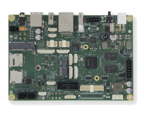
SBC-3.5-PX30 (JUNO - D23) is a Single Board Computer based on embedded Rockchip PX30 Processor, featuring Quad-Core ARM Cortex-A35 processor. The processor integrates a Mali-G31 GPU with High performance dedicated 2D processor, supporting OpenGL ES 1.1 / 2.0 / 3.2, Vulkan 1.0, OpenCL 2.0 and Open VG 1.1. Embedded VPU is able to support video decoding of the most common coding standard (MPEG-4, H.265/HEVC, H.264, VP8, VC-1). The board is completed with up to 4GB LPDDR4-3200 32-bit bus memory directly soldered on board and one eMMC 5.1 Flash Drive with up to 64GB of capacity. LVDS Single Channel interface and HDMI are supported. The RMII interface and Micrel KSZ8091 Ethernet Transceiver allow the implementation of a Fast Ethernet interface. The networking capabilities can be extended by WiFi+BT M.2 module and external modem module. The audio functionalities are managed by the AudioCodec embedded in the RK-809 PMIC. SBC-3.5-PX30 board is completed by a series of connectors with various interfaces (UART, SPI, I2C) managed by the microcontroller STM32F302VCT6.
More information about the board can be found at the SECO SBC-3.5-PX30 website.
Hardware
SECO SBC-3.5-PX30 provides the following hardware components:
STM32F302VCT6 - ARM® 32-bit Cortex® -M4 CPU with FPU - 256 KB Flash - 40 KB SRAM - 72 MHz max CPU frequency
2 User LEDs
16 GPI
16 GPO
4 U(S)ART - Modbus - RS485 - TTL Serial Debug - TTL Serial
8-channel General Purpose Timers
USB 2.0 full speed interface
CAN
I2C (up to 2)
SPI
More information about STM32F302VC can be found here:
Supported Features
The Zephyr stm32f3_seco_d23 board configuration supports the following hardware features:
Interface |
Controller |
Driver/Component |
|---|---|---|
NVIC |
on-chip |
nested vector interrupt controller |
UART |
on-chip |
serial port-polling; serial port-interrupt |
PINMUX |
on-chip |
pinmux |
GPIO |
on-chip |
gpio |
I2C |
on-chip |
i2c |
SPI |
on-chip |
spi |
USB |
on-chip |
USB device |
CAN |
on-chip |
CAN |
IWDG |
on-chip |
Independent WatchDoG |
PWM |
on-chip |
pwm |
Other hardware features are not yet supported on Zephyr porting.
Pin Mapping
SBC-3.5-PX30 has 6 GPIO controllers. These controllers are responsible for pin muxing, input/output, pull-up, etc.
For more details please refer to SECO SBC-3.5-PX30 board User Manual.
Default Zephyr Peripheral Mapping:
UART_1_TX : PA9 (debug config for UART_1)
UART_1_RX : PA10 (debug config for UART_1)
UART_1_TX : PC4 (alternate config for UART_1)
UART_1_RX : PC5 (alternate config for UART_1)
UART_2_TX : PD5
UART_2_RX : PD6
UART_2_CLK : PD7
UART_2_CTS : PD3
UART_2_RTS/DE : PD4
UART_3_TX : PC10
UART_3_RX : PC11
UART_3_CLK : PD10
UART_3_CTS : PD11
UART_3_RTS/DE : PD12
UART_5_TX : PC12
UART_5_RX : PD2
I2C1_SCL : PB6
I2C1_SDA : PB7
I2C2_SCL : PA9 (alternate config for UART_1)
I2C2_SDA : PA10 (alternate config for UART_1)
SPI1_NSS : PA4
SPI1_SCK : PB3
SPI1_MISO : PB4
SPI1_MOSI : PB5
SPI2_NSS : PB12
SPI2_SCK : PB13
SPI2_MISO : PB14
SPI2_MOSI : PB15
CAN1_RX : PB8
CAN1_TX : PB9
USB_DM : PA11
USB_DP : PA12
LD1 : PD8
LD2 : PD9
PWM : PA8
System Clock
SECO SBC-3.5-PX30 System Clock could be driven by internal or external oscillator, as well as main PLL clock. By default System clock is driven by PLL clock at 72 MHz, driven by an external oscillator at 8 MHz.
Serial Port
SECO SBC-3.5-PX30 has up to 4 U(S)ARTs. The Zephyr console output is assigned to UART1. Default settings are 115200 8N1. In debug configuration UART1 is connected to the flashing connector CN56.
UART2 provides Modbus interface to connector CN28. UART3 provides RS-485 interface to connectors CN57 and CN48. In alternative config, USART2 and USART3 are exposed to connector J2.
UART1 (in alternate config) and UART5 are connected to CN32.
I2C
SECO SBC-3.5-PX30 has up to 2 I2Cs. Both are present in connector CN33. I2C2 is available only on boards where DEBUG serial is not connected.
USB
SECO SBC-3.5-PX30 has a USB 2.0 full-speed device interface available through its connector CN31.
CAN
SECO SBC-3.5-PX30 has an onboard CAN transceiver (TJA1051T), and it is connected to both CN29 and CN30. PD0 is connected to EC_CAN_STBY.
SPI
SECO SBC-3.5-PX30 has two SPI lines: SPI1 is an internal SPI line connected to the main processor (Rockchip PX30) and SPI2 is connected to CN39.
Programming and Debugging
Flashing
Applications for the stm32f3_seco_d23 board configuration can be built and
flashed in the usual way (see Building an Application and
Run an Application for more details).
Flashing an application to SECO SBC-3.5-PX30
First, connect the SECO SBC-3.5-PX30 to your host computer using CN56 connector to an ST-Link. The pinout is (1-8): - VDD - UART1_TX - UART1_RX - BOOT_0 - SWDIO_JTMS - SWCLK_JTCK - EC_RST# - GND
Then build and flash your application.
Here is an example for the Hello World application.
# From the root of the zephyr repository
west build -b stm32f3_seco_d23 samples/hello_world
west flash
Run a serial host program to connect with your board.
$ minicom -D /dev/<tty device>
Replace <tty_device> with the port where the SBC-3.5-PX30 board can be found.
You should see the following message on the console:
Hello World! stm32f3_seco_d23