EFR32 BRD4187C (xG24-RB4187C)
Overview
The EFR32MG24 Mighty Gecko Radio Board is one of the two radio boards delivered with xG24-PK6010A Website. It contains a Wireless System-On-Chip from the EFR32MG24 family built on an ARM Cortex®-M33F processor with excellent low power capabilities.
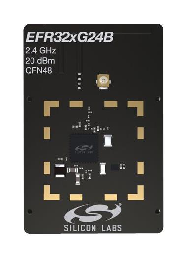
xG24-RB4187C (image courtesy of Silicon Labs)
The BRD4187C a.k.a. xG24-RB4187C radio board plugs into the Wireless Pro Kit Mainboard BRD4002A and is supported as one of EFR32 Radio Boards.
Hardware
EFR32MG24B220F1536IM48 Mighty Gecko SoC
CPU core: ARM Cortex®-M33 with FPU
Flash memory: 1536 kB
RAM: 256 kB
Transmit power: up to +20 dBm
Operation frequency: 2.4 GHz
Crystals for LFXO (32.768 kHz) and HFXO (39 MHz).
For more information about the EFR32MG24 SoC and BRD4187C board, refer to these documents:
Supported Features
The board configuration supports the following hardware features:
Interface |
Controller |
Driver/Component |
|---|---|---|
MPU |
on-chip |
memory protection unit |
NVIC |
on-chip |
nested vector interrupt controller |
SYSTICK |
on-chip |
systick |
COUNTER |
on-chip |
stimer |
FLASH |
on-chip |
flash memory |
GPIO |
on-chip |
gpio |
UART |
on-chip |
serial |
I2C |
on-chip |
i2c |
TRNG |
on-chip |
semailbox |
WATCHDOG |
on-chip |
watchdog |
Other hardware features are currently not supported by the port.
Connections and IOs
In the following table, the column Name contains Pin names. For example, PA2 means Pin number 2 on PORTA, as used in the board’s datasheets and manuals.
Name |
Function |
Usage |
|---|---|---|
PB2 |
GPIO |
LED0 |
PB4 |
GPIO |
LED1 |
PB1 |
GPIO |
Push Button 0 |
PB3 |
GPIO |
Push Button 1 |
PB0 |
GPIO |
Board Controller Enable VCOM_ENABLE |
PA8 |
USART0_TX |
UART Console VCOM_TX US0_TX |
PA9 |
USART0_RX |
UART Console VCOM_RX US0_RX |
The default configuration can be found in the defconfig file:
boards/arm/efr32_radio/efr32_radio_brd4187c_defconfig
System Clock
The EFR32MG24 SoC is configured to use the 39 MHz external oscillator on the board.
Serial Port
The EFR32MG24 SoC has one USART and two EUSARTs. USART0 is connected to the board controller and is used for the console.
Programming and Debugging
Please refer to Programming and Debugging EFR32 Radio Board for details on the supported debug interfaces.
Flashing
Connect the BRD4002A board with a mounted BRD4187C radio module to your host computer using the USB port.
Here is an example for the Hello World application.
# From the root of the zephyr repository
west build -b efr32_radio_brd4187c samples/hello_world
west flash
Open a serial terminal (minicom, putty, etc.) with the following settings:
Speed: 115200
Data: 8 bits
Parity: None
Stop bits: 1
Reset the board and you should see the following message in the terminal:
Hello World! efr32_radio_brd4187c