EFM32 Giant Gecko GG11 Starter Kit
Overview
The EFM32 Giant Gecko Starter Kit EFM32GG-STK3701A contains an MCU from the EFM32GG Series 1 family built on an ARM® Cortex®-M4F processor with excellent low power capabilities.
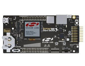
EFM32GG-SLSTK3701A (image courtesy of Silicon Labs)
Hardware
Advanced Energy Monitoring provides real-time information about the energy consumption of an application or prototype design.
Ultra low power 128x128 pixel color Memory-LCD
2 user buttons, 2 LEDs and a touch slider
Relative humidity, magnetic Hall Effect and inductive-capacitive metal sensor
USB interface for Host/Device/OTG
32 Mb Quad-SPI Flash memory
SD card slot
RJ-45 Ethernet jack
2 digital microphones
On-board Segger J-Link USB debugger
For more information about the EFM32GG11 SoC and EFM32GG-STK3701A board:
Supported Features
The efm32gg_stk3701a board configuration supports the following hardware features:
Interface |
Controller |
Driver/Component |
|---|---|---|
MPU |
on-chip |
memory protection unit |
COUNTER |
on-chip |
rtcc |
ETHERNET |
on-chip |
ethernet |
FLASH |
on-chip |
flash memory |
GPIO |
on-chip |
gpio |
I2C |
on-chip |
i2c port-polling |
NVIC |
on-chip |
nested vector interrupt controller |
SYSTICK |
on-chip |
systick |
UART |
on-chip |
serial port-polling; serial port-interrupt |
The default configuration can be found in the defconfig file:
boards/arm/efm32gg_stk3701a/efm32gg_stk3701a_defconfig
Other hardware features are currently not supported by the port.
Connections and IOs
The EFM32GG11 SoC has nine GPIO controllers (PORTA to PORTI), all of which are currently enabled for the EFM32GG-STK3701A board.
In the following table, the column Name contains pin names. For example, PE1 means pin number 1 on PORTE, as used in the board’s datasheets and manuals.
Name |
Function |
Usage |
|---|---|---|
PH10 |
GPIO |
LED0 red |
PH11 |
GPIO |
LED0 green |
PH12 |
GPIO |
LED0 blue |
PH13 |
GPIO |
LED1 red |
PH14 |
GPIO |
LED1 green |
PH15 |
GPIO |
LED1 blue |
PC8 |
GPIO |
Push Button PB0 |
PC9 |
GPIO |
Push Button PB1 |
PE1 |
GPIO |
Board Controller Enable EFM_BC_EN |
PH4 |
UART_TX |
UART TX Console VCOM_TX US0_TX #4 |
PH5 |
UART_RX |
UART RX Console VCOM_RX US0_RX #4 |
PI4 |
I2C_SDA |
SENSOR_I2C_SDA I2C2_SDA #7 |
PI5 |
I2C_SCL |
SENSOR_I2C_SCL I2C2_SCL #7 |
System Clock
The EFM32GG11 SoC is configured to use the 50 MHz external oscillator on the board.
Serial Port
The EFM32GG11 SoC has six USARTs, two UARTs and two Low Energy UARTs (LEUART). USART4 is connected to the board controller and is used for the console.
Programming and Debugging
Note
Before using the kit the first time, you should update the J-Link firmware from J-Link-Downloads
Flashing
The EFM32GG-STK3701A includes an J-Link serial and debug adaptor built into the board. The adaptor provides:
A USB connection to the host computer, which exposes a mass storage device and a USB serial port.
A serial flash device, which implements the USB flash disk file storage.
A physical UART connection which is relayed over interface USB serial port.
Flashing an application to EFM32GG-STK3701A
The sample application Hello World is used for this example. Build the Zephyr kernel and application:
# From the root of the zephyr repository
west build -b efm32gg_stk3701a samples/hello_world
Connect the EFM32GG-STK3701A to your host computer using the USB port and you should see a USB connection which exposes a mass storage device(STK3701A) and a USB Serial Port. Copy the generated zephyr.bin to the STK3701A drive.
Open a serial terminal (minicom, putty, etc.) with the following settings:
Speed: 115200
Data: 8 bits
Parity: None
Stop bits: 1
Reset the board and you’ll see the following message on the corresponding serial port terminal session:
Hello World! efm32gg_stk3701a