Cortex-M Trace Reference Board V1.2
Overview
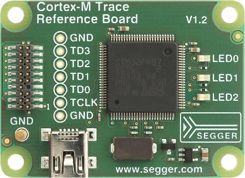
The Cortex-M Trace Reference Board V1.2 (SEGGER-TRB-STM32F407 for short) board is a reference board, based on the ST Microelectronics STM32F407VE ARM Cortex-M4 CPU, to test hardware tracing with the SEGGER Trace-Pro debuggers. It is not meant for general prototype development because it is extremely limited when it comes to IO, and only has 3 LEDs.
SEGGER-TRB-STM32F407
Hardware
Information about the board can be found at the SEGGER website . The ST STM32F407VE website contains the processor’s information and the datasheet.
Supported Features
The SEGGER-TRB-STM32F407 board configuration supports the following hardware features:
Interface |
Controller |
Driver/Component |
|---|---|---|
NVIC |
on-chip |
nested vectored interrupt controller |
SYSTICK |
on-chip |
system clock |
GPIO |
on-chip |
gpio |
WATCHDOG |
on-chip |
independent watchdog |
COUNTER |
on-chip |
rtc |
RNG |
on-chip |
True Random number generator |
Other hardware features have not been enabled yet for this board.
Pin Mapping
LED
LED0 (green) = PA8
LED1 (green) = PA9
LED2 (green) = PA10
External Connectors
JTAG/SWD debug
PIN # |
Signal Name |
Pin # |
Signal Name |
|---|---|---|---|
1 |
VTref |
2 |
SWDIO/TMS |
3 |
GND |
4 |
SWCLK/TCK |
5 |
GND |
6 |
SWO/TDO |
7 |
— |
8 |
TDI |
9 |
NC |
10 |
nRESET |
11 |
5V-Supply |
12 |
TRACECLK |
13 |
5V-Supply |
14 |
TRACEDATA[0] |
15 |
GND |
16 |
TRACEDATA[1] |
17 |
GND |
18 |
TRACEDATA[2] |
19 |
GND |
20 |
TRACEDATA[3] |
System Clock
SEGGER-STM32F407-TRB has one external oscillator. The frequency of the main clock is 12 MHz. The processor can setup HSE to drive the master clock, which can be set as high as 168 MHz.
Programming and Debugging
The SEGGER-TRB-STM32F407 board is specially designed to test the SEGGER Trace-Pro debuggers, so this example assumes a J-Trace or J-Link is used.
Flashing an application to the SEGGER-TRB-STM32F407
Connect the J-Trace/J-Link USB dongle to your host computer and to the JTAG port of the SEGGER-TRB-STM32F407 board. Then build and flash an application.
Here is an example for the Blinky application.
# From the root of the zephyr repository
west build -b segger_trb_stm32f407 samples/basic/blinky
west flash
After resetting the board, you should see LED0 blink with a 1 second interval.
Debugging
Here is an example for the Blinky application.
# From the root of the zephyr repository
west build -b segger_trb_stm32f407 samples/basic/blinky
west debug