Arduino Nano 33 BLE (Sense)
Overview
The Arduino Nano 33 BLE is designed around Nordic Semiconductor’s nRF52840 ARM Cortex-M4F CPU. Arduino sells 2 variants of the board, the plain BLE [1] type and the BLE Sense [2] type. The “Sense” variant is distinguished by the inclusion of more sensors, but otherwise both variants are the same.
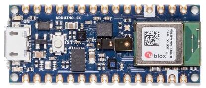
The Sense variant of the board
Hardware
Supported Features
The package is configured to support the following hardware:
Interface |
Controller |
Driver/Component |
|---|---|---|
ADC |
on-chip |
adc |
CLOCK |
on-chip |
clock_control |
FLASH |
on-chip |
flash |
GPIO |
on-chip |
gpio |
I2C0 |
on-chip |
i2c |
I2C1 |
on-chip |
i2c |
MPU |
on-chip |
arch/arm |
NVIC |
on-chip |
arch/arm |
PWM |
on-chip |
pwm |
RADIO |
on-chip |
Bluetooth, ieee802154 |
RTC |
on-chip |
system clock |
SPI |
on-chip |
spi |
UART |
on-chip |
serial |
USB |
on-chip |
usb |
WDT |
on-chip |
watchdog |
Other hardware features have not been enabled yet for this board.
Notably, this includes the PDM (microphone) interface.
Connections and IOs
The schematic [3] will tell you everything you need to know about the pins.
The I2C pull-ups are enabled by setting pin P1.00 high. This is automatically
done at system init. The pin is specified in the zephyr,user Devicetree node
as pull-up-gpios.
Programming and Debugging
This board requires the Arduino variant of bossac. You will not be able to flash with the bossac included with the zephyr-sdk, or using shumatech’s mainline build.
You can get this variant of bossac with one of two ways:
Building the binary from the Arduino source tree
Downloading the Arduino IDE
Install the board support package within the IDE
Change your IDE preferences to provide verbose logging
Build and flash a sample application, and read the logs to figure out where Arduino stored bossac.
In most Linux based systems the path is
$HOME/.arduino15/packages/arduino/tools/bossac/1.9.1-arduino2/bossac.
Once you have a path to bossac, you can pass it as an argument to west:
west flash --bossac="<path to the arduino version of bossac>"
For example
west flash --bossac=$HOME/.arduino15/packages/arduino/tools/bossac/1.9.1-arduino2/bossac
On Windows you need to use the bossac.exe from the Arduino IDE [6]
You will also need to specify the COM port using the –bossac-port argument:
west flash --bossac=%USERPROFILE%\AppData\Local\Arduino15\packages\arduino\tools\bossac\1.9.1-arduino2\bossac.exe --bossac-port="COMx"
Flashing
Attach the board to your computer using the USB cable, and then
west build -b arduino_nano_33_ble samples/basic/blinky
Double-tap the RESET button on your board. Your board should disconnect, reconnect, and there should be a pulsing orange LED near the USB port.
Then, you can flash the image using the above script.
You should see the red LED blink.
Debugging
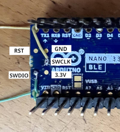
You can debug an application on the board with a debug adapter that supports CMSIS-DAP. This board has the SWD connector for debugging but exposes it as a test pad pattern (not a connector) on the back side of the PCB. So, It needs bit of difficult soldering. At a minimum, SWDIO and SWCLK need soldering (As shown in the picture). GND, 3.3V, and RESET are also available in the DIP connector, therefore it may be easier to connect using the DIP connector instead of soldering to them.
After connecting the debug adapter, you can debug it the usual way. Type the following command will start debugging.
# From the root of the zephyr repository
west build -b arduino_nano_33_ble samples/basic/blinky
west debug
Debugging with TRACE32 (GDB Front-End)
Lauterbach provides GDB Debug version TRACE32 for Arduino Nano 33 BLE [4]. That license ties to Arduino Nano 33 BLE hardware serial number, it also works with the ZephyrRTOS.
Follow the instruction of the tutorial for Arduino Lauterbach TRACE32 GDB Front-End Debugger for Nano 33 BLE to install the TRACE32.
After installing the TRACE32, You should set the environmental variable T32_DIR.
If you installed TRACE32 into the home directory, run the following command.
(It is a good idea to put in the login script.)
export T32_DIR="~/T32Arduino"
The TRACE32 is TRACE32 as GDB Front-End [5] version. Required to run the GDB server before launching TRACE32 with the following command.
west build -b arduino_nano_33_ble samples/basic/blinky
west debugserver
Execute the following command after launching the GDB server to run the TRACE32 and connect the GDB server.
west debug --runner=trace32 -- gdbRemote=:3333
The TRACE32 script handles arguments after the -- sign.
You can set the following options.
Name |
Required? |
Description |
gdbRemote |
Required |
Set the GDB server address or device file of the serial port.
It can take <hostname>:<port> or <devicename>.
e.g.)
gdbRemote=localhost:3333, gdbRemote=/dev/ttyACM0 |
terminal |
Optional |
Set the device file of the serial port connected to the target console.
e.g.)
terminal=/dev/ttyACM1 |
userScript |
Optional |
Set user script that runs after system script execute done.
e.g.)
userScript="./user.cmm" |