Adafruit Grand Central M4 Express
Overview
The Adafruit Grand Central M4 Express is an ARM development board with the form factor of an Arduino Mega. It features 70 GPIO pins, a microSDHC slot and 8MiB of QSPI Flash.
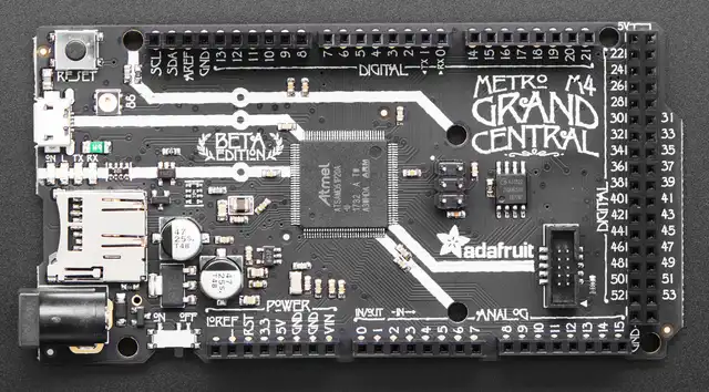
Adafruit Grand Central M4 Express (Credit: Kattni Rembor / Adafruit)
Hardware
ATSAMD51P20A ARM Cortex-M4F processor at 120 MHz
1024 KiB of flash memory and 256 KiB of RAM
8 MiB of QSPI flash
A red user LED
A RGB “NeoPixel” / WS2812B LED
A microSDHC slot (connected via SPI)
Native USB port
Supported Features
The adafruit_grand_central_m4_express board configuration supports the following hardware features:
Interface |
Controller |
Driver/Component |
|---|---|---|
NVIC |
on-chip |
Nested vector interrupt controller |
SYSTICK |
on-chip |
SysTick |
WDT |
on-chip |
Watchdog |
GPIO |
on-chip |
I/O ports, User LED |
UART |
on-chip |
Serial ports, Console |
SPI |
on-chip |
SPI ports, microSDHC slot |
TRNG |
on-chip |
True Random Number Generator |
RTC |
on-chip |
Real-Time Counter |
USB |
on-chip |
USB device |
WDT |
on-chip |
Watchdog Timer |
Other hardware features are not currently supported by Zephyr.
The default configuration can be found in the Kconfig file boards/arm/adafruit_grand_central_m4_express/adafruit_grand_central_m4_express_defconfig.
Connections and IOs
The Adafruit Learning System [1] has detailed information about the board including pinouts [2] and the schematics [3].
System Clock
The SAMD51 MCU is configured to use the 32.768 kHz external oscillator with the on-chip PLL generating the 120 MHz system clock.
Serial Port
The SAMD51 MCU has 8 SERCOM based UARTs. On the Grand Central, SERCOM0 is the Zephyr console and is available on RX(PB25) and TX(PB24).
SPI Port
The SAMD51 MCU has 8 SERCOM based SPIs. On the Grand Central, SERCOM7 has been set into SPI mode to connect to devices over the SCK(PD09), MOSI(PD08), and MISO(PD11) pins. Additionally SERCOM2 has been configured as SPI to access the microSDHC card.
I2C Port
The SAMD51 MCU has 8 SERCOM based I2Cs. On the Grand Central, SERCOM3 has been configured as I2C to connect to devices over the SCL(PB21) and SDA(PB20) pins.
USB Device Port
The SAMD51 MCU has a USB device port that can be used to communicate with a host PC. See the USB device support samples sample applications for more, such as the USB CDC-ACM sample which sets up a virtual serial port that echos characters back to the host PC.
Programming and Debugging
The Grand Central ships with a BOSSA compatible UF2 bootloader. The bootloader can be entered by quickly tapping the reset button twice.
Flashing
Build the Zephyr kernel and the Hello World sample application:
west build -b adafruit_grand_central_m4_express samples/hello_world
Connect the Grand Central to your host computer using USB.
Connect a 3.3 V USB to serial adapter to the board and to the host. See the Serial Port section above for the board’s pin connections.
Run your favorite terminal program to listen for output. Under Linux the terminal should be
/dev/ttyUSB0. For example:$ minicom -D /dev/ttyUSB0 -o
The -o option tells minicom not to send the modem initialization string. Connection should be configured as follows:
Speed: 115200
Data: 8 bits
Parity: None
Stop bits: 1
Tap the reset button twice quickly to enter bootloader mode
Flash the image:
west build -b adafruit_grand_central_m4_express samples/hello_world
west flash
You should see “Hello World! adafruit_grand_central_m4_express” in your terminal.
Debugging
In addition to the built-in bootloader, the Grand Central can be flashed and debugged using a SWD probe such as the Segger J-Link.
Connect the probe to the board using the 10-pin SWD interface.
Flash the image:
west build -b adafruit_grand_central_m4_express samples/hello_world
west flash -r openocd
Start debugging:
west build -b adafruit_grand_central_m4_express samples/hello_world
west debug