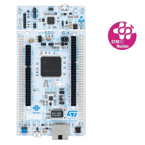
ST Nucleo F429ZI
Overview
The Nucleo F429ZI board features an ARM Cortex-M4 based STM32F429ZI MCU with a wide range of connectivity support and configurations. Here are some highlights of the Nucleo F429ZI board:
STM32 microcontroller in LQFP144 package
LSE crystal: 32.768 kHz crystal oscillator
USB OTG
Ethernet compliant with IEEE-802.3-2002
Two types of extension resources:
ST Zio connector including: support for Arduino* Uno V3 connectivity (A0 to A5, D0 to D15) and additional signals exposing a wide range of peripherals
ST morpho extension pin headers for full access to all STM32 I/Os
On-board ST-LINK/V2-1 debugger/programmer with SWD connector
Flexible board power supply:
5 V from ST-LINK/V2-1 USB VBUS
External power sources: 3.3 V and 7 - 12 V on ST Zio or ST morpho connectors, 5 V on ST morpho connector
Three user LEDs
Two push-buttons: USER and RESET
More information about the board can be found at the Nucleo F429ZI website.
Hardware
The Nucleo F429ZI provides the following hardware components:
STM32F429ZIT6 in LQFP144 package
ARM® 32-bit Cortex® -M4 CPU with FPU
180 MHz max CPU frequency
VDD from 1.8 V to 3.6 V
2 MB Flash
256+4 KB SRAM including 64-Kbyte of core coupled memory
GPIO with external interrupt capability
3x12-bit ADC with 24 channels
2x12-bit D/A converters
RTC
Advanced-control Timer
General Purpose Timers (17)
Watchdog Timers (2)
USART/UART (4/4)
I2C (3)
SPI (6)
SDIO
2xCAN
USB 2.0 OTG FS with on-chip PHY
USB 2.0 OTG HS/FS with dedicated DMA, on-chip full-speed PHY and ULPI
10/100 Ethernet MAC with dedicated DMA
8- to 14-bit parallel camera
CRC calculation unit
True random number generator
DMA Controller
More information about STM32F429ZI can be found here:
Supported Features
The Zephyr nucleo_f429zi board configuration supports the following hardware features:
Interface |
Controller |
Driver/Component |
|---|---|---|
NVIC |
on-chip |
nested vector interrupt controller |
UART |
on-chip |
serial port-polling; serial port-interrupt |
PINMUX |
on-chip |
pinmux |
GPIO |
on-chip |
gpio |
ETHERNET |
on-chip |
Ethernet |
PWM |
on-chip |
pwm |
I2C |
on-chip |
i2c |
USB |
on-chip |
usb |
SPI |
on-chip |
spi |
WATCHDOG |
on-chip |
independent watchdog |
ADC |
on-chip |
adc |
DAC |
on-chip |
DAC Controller |
DMA |
on-chip |
Direct Memory Access |
die-temp |
on-chip |
die temperature sensor |
Other hardware features are not yet supported on this Zephyr port.
The default configuration can be found in the defconfig file:
boards/arm/nucleo_f429zi/nucleo_f429zi_defconfig
Connections and IOs
The Nucleo F429ZI Board has 8 GPIO controllers. These controllers are responsible for pin muxing, input/output, pull-up, etc.
Available pins:
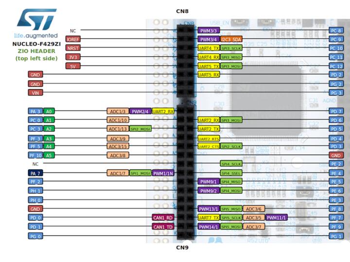
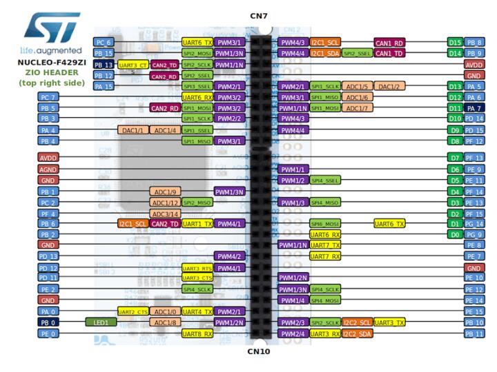
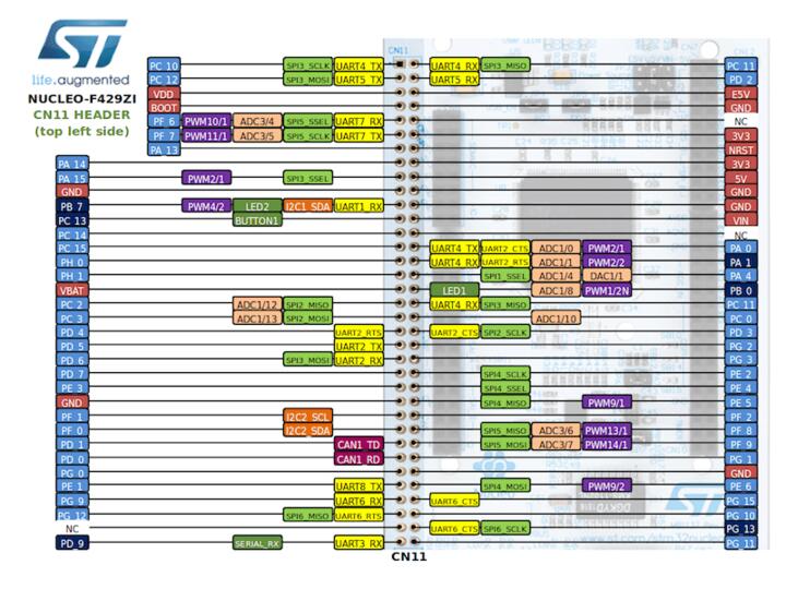
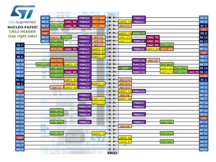
For more details please refer to STM32 Nucleo-144 board User Manual.
Default Zephyr Peripheral Mapping:
The Nucleo F429ZI board features a ST Zio connector (extended Arduino Uno V3) and a ST morpho connector. Board is configured as follows
UART_3 TX/RX : PD8/PD9 (ST-Link Virtual Port Com)
UART_6 TX/RX : PG14/PG9 (Arduino Serial)
I2C1 SCL/SDA : PB8/PB9 (Arduino I2C)
SPI1 NSS/SCK/MISO/MOSI : PD14/PA5/PA6/PA7 (Arduino SPI)
PWM_2_CH1 : PE13
ETH : PA1, PA2, PA7, PB13, PC1, PC4, PC5, PG11, PG13
USER_PB : PC13
LD1 : PB0
LD2 : PB7
LD3 : PB14
USB DM : PA11
USB DP : PA12
ADC1 : PA0
System Clock
The Nucleo F429ZI System Clock could be driven by an internal or external oscillator, as well as by the main PLL clock. By default System clock is driven by PLL clock at 180MHz, driven by an 8MHz high speed external clock.
Serial Port
The Nucleo F429ZI board has 8 UARTs. The Zephyr console output is assigned to UART3. Default settings are 115200 8N1.
Programming and Debugging
The Nucleo F429ZI board includes an ST-LINK/V2-1 embedded debug tool interface. This interface is supported by the openocd version included in Zephyr SDK.
Flash partitions for MCUBoot bootloader
The on-board STM32F429ZI MCU has 2MBs of internal flash memory. To use MCUboot,
define a Zephyr partition table for the flash memory in
its devicetree file nucleo_f429zi.dts. As a reference, a partition table for
MCUBoot is already defined in the devicetree file, with these settings:
MCUBoot bootloader partition takes 64K bytes.
Zephyr settings partition takes 64K bytes.
Application image takes 256K bytes in Slot 0 partition.
Updating image takes another 256K bytes in Slot 1 partition.
A scratch partition with 128K is required for image swap.
A specific application can adjust each partition size based on its needs.