Ruuvi RuuviTag
Overview
RuuviTag is an advanced battery-operated open-source Bluetooth enabled sensor beacon platform capable of sending temperature, humidity, pressure, and motion information over Bluetooth Low Energy.
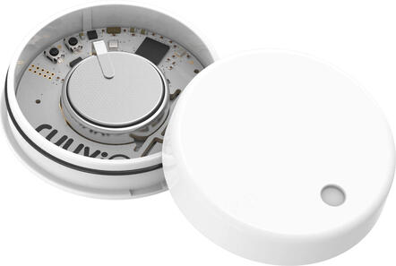
RUUVI RuuviTag (Credit: https://ruuvi.com/)
More information about the board can be found at the ruuvitag website [1].
Hardware
RuuviTag’s have the following physical features:
Nordic Semiconductor nRF52832 System-on-Chip
STMicroelectronics LIS2DH12 accelerometer
Bosch BME 280 temperature + relative air humidity + air pressure sensor
NFC™-A tag antenna
1000mAh CR2477 battery
2 buttons
1 Green LED
1 Red LED
IP67 Enclosure
Long range RF antenna
Supported Features
Interface |
Controller |
Driver/Component |
|---|---|---|
ADC |
on-chip |
adc |
CLOCK |
on-chip |
clock_control |
FLASH |
on-chip |
flash |
GPIO |
on-chip |
gpio |
MPU |
on-chip |
arch/arm |
NVIC |
on-chip |
arch/arm |
RADIO |
on-chip |
Bluetooth |
RTC |
on-chip |
system clock |
SPI |
on-chip |
spi |
UART |
on-chip |
serial |
WDT |
on-chip |
watchdog |
Humidity, Temp & Air Pressure |
on-board |
bme280 |
Acc |
on-board |
lis2dh12 |
Connections and IOs
LED
LED0 (red) = P0.17
LED1 (green) = P0.19
Pin descriptions
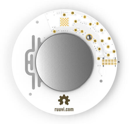
2 = P0.29 = SPI_SCK
3 = P0.28 = SPI_MISO
10 = P0.04 = GPIO (can be used as a GPIO / ADC pin)
11 = P0.05 = GPIO (can be used as a GPIO / ADC pin)
12 = P0.25 = SPI_MOSI
13 = P0.19 = LED2 (green) / GPIO (can be used as a GPIO pin but the LED will blink)
14 = P0.17 = LED1 (red) / GPIO (can be used as a GPIO pin but the LED will blink)
15 = P0.13 = Button / GPIO (can be used as a GPIO pin)
16 = GND (Battery’s negative contact)
17 = Battery’s positive contact
18 = Battery’s positive contact
19 = SWDIO
20 = SWDCLK
21 = P0.18 = SWO / GPIO (can be used as a GPIO pin)
22 = P0.21 = Reset / GPIO (can be used as a GPIO pin if no need to reset the device)
23 = GND (Battery’s negative contact)
24 = P0.31 = GPIO (can be used as a GPIO / ADC pin)
25 = P0.30 = GPIO (can be used as a GPIO / ADC pin)
GPIO = General Purpose Input Output pin
P1 = Standard 10-pin ARM Cortex debug connector (on RuuviTag Rev.B1-B5)
1 = VDD
2 = SWDIO
3 = GND (Battery’s negative contact)
4 = SWDCLK
5 = GND (Battery’s negative contact)
6 = SWO
7 = No Connect
8 = No Connect
9 = GND (Battery’s negative contact)
10 = Reset
P1 = TC2030 TagConnect (on RuuviTag Rev.B6)
1 = Battery’s positive contact
2 = SWDIO
3 = Reset
4 = SWDCLK
5 = GND (Battery’s negative contact)
6 = SWO
Programming and Debugging
Flashing
Build and flash applications as usual (see Building an Application and Run an Application for more details).
The easiest way to flash Zephyr onto a RuuviTag requires an external Ruuvi DEVKIT. More information about the board can be found at the ruuvitag devkit [2].
Once your tag is connected to the DEVKIT and connected to your PC, build and flash the application in the usual way.
# From the root of the zephyr repository
west build -b ruuvi_ruuvitag samples/basic/blinky
west flash
Advanced users may want to program the RuuviTag without the DEVKIT, this can be achieved via the SWDIO and SWDCLK pins located on the back of the RuuviTag.
Debugging
If using the Ruuvi DEVKIT refer to the Nordic nRF5x Segger J-Link page to learn about debugging Nordic boards with a Segger IC.