Seeed Studio LoRa-E5 Dev Board
Overview
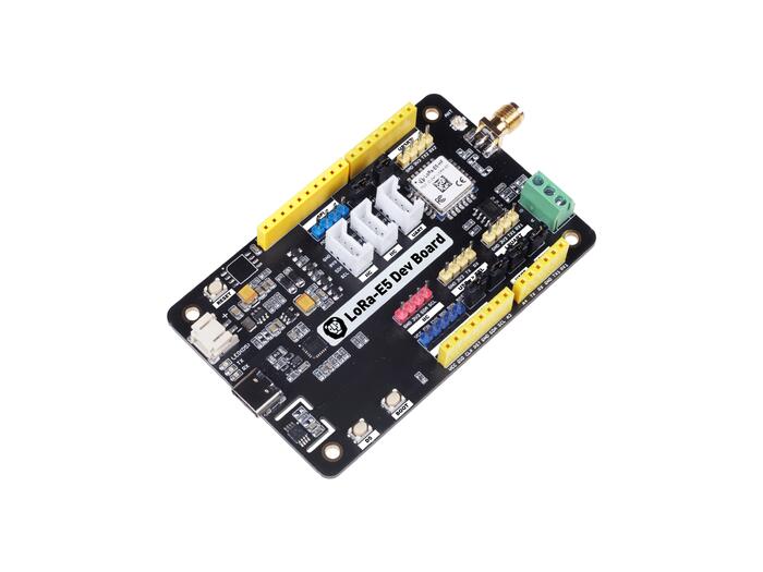
The LoRa-E5 Dev Board is a compact board for the evaluation of the Seeed Studio LoRa-E5 STM32WLE5JC module. The LoRa-E5-HF STM32WLE5JC Module supports multiple LPWAN protocols on the 868/915MHz frequency bands with up to 20.8dBm output power at 3.3V. All GPIOs of the LoRa-E5 Module are laid out supporting various data protocols and interfaces including RS-485 and Grove.
Hardware
The boards LoRa-E5 Module packages a STM32WLE5JC SOC, a 32MHz TCXO, and a 32.768kHz crystal oscillator in a 28-pin SMD package. This STM32WLEJC SOC is powered by ARM Cortex-M4 core and integrates Semtech SX126X LoRa IP to support (G)FSK, BPSK, (G)MSK, and LoRa modulations.
LoRa-E5 STM32WLE5JC Module with STM32WLE5JC multiprotocol LPWAN single-core 32-bit microcontroller (Arm® Cortex®-M4 at 48 MHz) in 28-pin SMD package featuring:
Ultra-low-power MCU
RF transceiver (150 MHz to 960 MHz frequency range) supporting LoRa®, (G)FSK, (G)MSK, and BPSK modulations
256-Kbyte Flash memory and 64-Kbyte SRAM
Hardware encryption AES256-bit and a True random number generator
1 user LED
1 user, 1 boot, and 1 reset push-button
32.768 kHz LSE crystal oscillator
32 MHz HSE oscillator
1 LM75A Temperature Sensor
1 SPI-Flash Bonding Pad(not populated)
Board connectors:
USB Type-C connector
JST2.0 Battery connector (3-5V)
3 Grove connectors(2x IIC and 1x UART)
RS-485 connector
SMA-K and IPEX antenna connectors
Delivered with SMA antenna (per default IPEX connector is disconnected)
Flexible power-supply options: USB Type C, JST2.0, 2x AA 3V Battery Holder, or external sources via header.
Switchable 3.3V and 5V power rails.
Comprehensive free software libraries and examples available with the STM32CubeWL MCU Package
Support of a wide choice of Integrated Development Environments (IDEs) including IAR Embedded Workbench®, MDK-ARM, and STM32CubeIDE
Suitable for rapid prototyping of end nodes based on LoRaWAN, Sigfox, wM-Bus, and many other proprietary protocols
More information about the board can be found at the LoRa-E5 Dev Board Wiki.
More information about LoRa-E5 STM32WLE5JC Module can be found here:
Supported Features
The Zephyr LoRa-E5 Dev Board configuration supports the following hardware features:
Interface |
Controller |
Driver/Component |
|---|---|---|
ADC |
on-chip |
adc |
AES |
on-chip |
crypto |
COUNTER |
on-chip |
rtc |
CLOCK |
on-chip |
reset and clock control |
FLASH |
on-chip |
flash |
GPIO |
on-chip |
gpio |
I2C |
on-chip |
i2c |
MPU |
on-chip |
arch/arm |
NVIC |
on-chip |
arch/arm |
PINMUX |
on-chip |
pinmux |
RADIO |
on-chip |
LoRa |
SPI |
on-chip |
spi |
UART |
on-chip |
serial port-polling; serial port-interrupt |
WATCHDOG |
on-chip |
independent watchdog |
Other hardware features are not yet supported on this Zephyr port.
The default configuration can be found in the defconfig and dts files:
Connections and IOs
LoRa-E5 Dev Board has 4 GPIO controllers. These controllers are responsible for pin muxing, input/output, pull-up, etc.
Available pins:
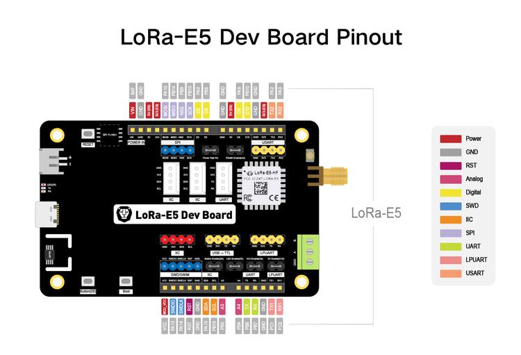
Default Zephyr Peripheral Mapping:
LPUART_1 TX : PC1
LPUART_1 RX : PC0
USART_1 TX : PB6
USART_1 RX : PB7
USART_2 TX : PA2
USART_2 RX : PA3
I2C_2_SCL : PB15
I2C_2_SDA : PA15
SPI_2_NSS : PB9
SPI_2_SCK : PB13
SPI_2_MISO : PB14
SPI_2_MOSI : PA10
BOOT_PB : PB13
USER_PB : PA0
LED_1 : PB5
ADC1 IN2 : PB3
Default Zephyr Peripheral to Connector Mapping:
RS-485: USART_2
grove_serial: USART_1
grove_i2c: I2C_2
Power Rails
The board has multiple power rails, which are always turned on in the default configuration.
Name |
Derived from |
Controlled by |
|---|---|---|
MAIN |
battery, USB, … |
Always on |
VCC |
MAIN |
Always on |
5V |
MAIN |
SOC pin PB10 |
3V3 |
VCC |
SOC pin PA9 |
A list of the devices and their power rails:
Device |
Rail |
|---|---|
STM32WLE5JC |
VCC |
RS-485 Transceiver |
3V3 |
System Clock
LoRa-E5 Development board System Clock could be driven by the low-power internal(MSI), High-speed internal(HSI) or High-speed external(HSE) oscillator, as well as main PLL clock. By default System clock is driven by the MSI clock at 48MHz.
Programming and Debugging
Applications for the lora_e5_dev_board board configuration can be built the
usual way (see Building an Application).
In the factory the module is flashed with an DFU bootloader, an AT command
firmware, and the read protection level 1 is enabled.
So before you can program a zephyr application to the module for the first time
you have to reset the read protection to level 0.
In case you use an st-link debugger you can use the STM32CubeProgrammer GUI to
set the RDP option byte to AA,
or use the STM32_Programmer_CLI passing the --readunprotect command
to perform this read protection regression.
The RDP level 1 to RDP level 0 regression will erase the factory programmed AT
firmware, from which seeed has neither released the source code nor a binary.
Also, note that on the module the BOOT0 pin of the SOC is not accessible,
so the system bootloader will only be executed if configured in the option bytes.
Flashing
The LoRa-E5 Dev Board does not include a on-board debug probe.
But the module can be debugged by connecting an external debug probe to the
blue 2.54mm header labeled SWIM/SWD.
Depending on the external probe used, openocd, the stm32cubeprogrammer,
pyocd, blackmagic, or jlink runner can be used to flash the board.
Additional notes:
Pyocd: For STM32WL support Pyocd needs additional target information, which can be installed by adding “pack” support with the following pyocd command:
$ pyocd pack --update
$ pyocd pack --install stm32wl
Flashing an application to LoRa-E5 Dev board
Connect the LoRa-E5 to your host computer using the external debug probe. Then build and flash an application. Here is an example for the Hello World application.
Run a serial host program to connect with your board:
Per default the console on usart1 is available on the USB Type C connector
via the built-in USB to UART converter.
$ picocom --baud 115200 /dev/ttyACM0
Then build and flash the application.
# From the root of the zephyr repository
west build -b lora_e5_dev_board samples/hello_world
west flash
Debugging
You can debug an application in the usual way. Here is an example for the Blinky application.
# From the root of the zephyr repository
west build -b lora_e5_dev_board samples/basic/blinky
west debug