STM32 Minimum Development Board
Overview
The STM32 Minimum Development Board, is a popular and inexpensive breadboard-friendly breakout board for the STM32F103x8 CPU. There are two variants of the board:
Blue Pill Board
Black Pill Board
Zephyr applications can use the stm32_min_dev_blue or stm32_min_dev_black board configuration to use these boards.
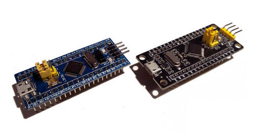
STM32 Minimum Development Board
As the name suggests, these boards have the bare minimum components required to power on the CPU. For practical use, you’ll need to add additional components and circuits using a breadboard, for example.
Pin Mapping
This port is a starting point for your own customizations and not a complete port for a specific board. Most of the GPIOs on the STM32 SoC has been exposed in the external header with silk screen labels that match the SoC’s pin names.
Each board vendor has their own variations in pin mapping on their boards’ external connectors and placement of components. Many vendors use port PC13/PB12 for connecting an LED, so only this device is supported by our Zephyr port. Additional device support is left for the user to implement.
More information on hooking up peripherals and lengthy how to articles can be found at EmbedJournal.
The pinout diagram of STM32 Minimum Development Blue Pill board can be seen below. The Black Pill’s one is similar:
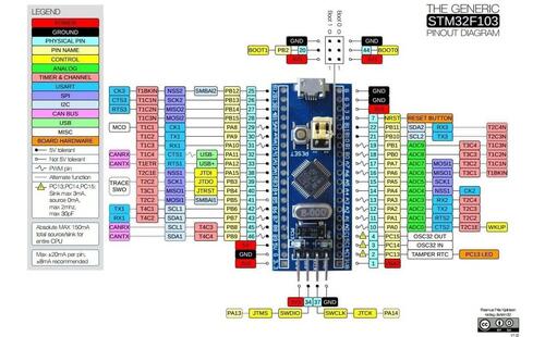
Pinout for STM32 Minimum Development Blue Pill Board
STLinkV2 connection:
The board can be flashed by using STLinkV2 with the following connections.
Pin |
STLINKv2 |
|---|---|
G |
GND |
CLK |
Clock |
IO |
SW IO |
V3 |
VCC |
Boot Configuration
The boot configuration for this board is configured through jumpers on B0 (Boot 0) and B1 (Boot 1). The pins B0 and B1 are present in between logic 0 and 1 lines. The silk screen on the PCB reads BX- or BX+ to indicate 0 and 1 logic lines for B0 and B1 respectively.
Boot 1 |
Boot 0 |
Boot Mode |
Aliasing |
|---|---|---|---|
X |
0 |
Main Flash Memory |
Main flash memory is selected as boot space |
0 |
1 |
System Memory |
System memory is selected as boot space |
1 |
1 |
Embedded SRAM |
Embedded SRAM is selected as boot space |
Supported Features
The stm32_min_dev board configuration supports the following hardware features:
Interface |
Controller |
Driver/Component |
|---|---|---|
NVIC |
on-chip |
nested vectored interrupt controller |
SYSTICK |
on-chip |
system clock |
UART |
on-chip |
serial port |
GPIO |
on-chip |
gpio |
I2C |
on-chip |
i2c |
PWM |
on-chip |
pwm |
SPI |
on-chip |
spi |
USB |
on-chip |
USB device |
ADC |
on-chip |
adc |
Other hardware features have not been enabled yet for this board.
Connections and IOs
Default Zephyr Peripheral Mapping:
UART_1 TX/RX: PA9/PA10
UART_2 TX/RX: PA2/PA3
UART_3 TX/RX: PB10/PB11
I2C_1 SCL/SDA : PB6/PB7
I2C_2 SCL/SDA : PB10/PB11
PWM_1_CH1: PA8
SPI_1 NSS_OE/SCK/MISO/MOSI: PA4/PA5/PA6/PA7
SPI_2 NSS_OE/SCK/MISO/MOSI: PB12/PB13/PB14/PB15
USB_DC DM/DP: PA11/PA12
ADC_1: PA0
System Clock
The on-board 8Mhz crystal is used to produce a 72Mhz system clock with PLL.
Serial Port
STM32 Minimum Development Board has 3 U(S)ARTs. The Zephyr console output is assigned to UART_1. Default settings are 115200 8N1.
On-Board LEDs
The board has one on-board LED that is connected to PB12/PC13 on the black/blue variants respectively.
Programming and Debugging
Applications for the stm32_min_dev_(blue|black) board configuration can be
built and flashed in the usual way (see Building an Application and
Run an Application for more details).
Flashing
Here is an example for the Blinky application.
# From the root of the zephyr repository
west build -b stm32_min_dev_blue samples/basic/blinky
west flash
Debugging
You can debug an application in the usual way. Here is an example for the Hello World application.
# From the root of the zephyr repository
west build -b stm32_min_dev_blue samples/hello_world
west debug