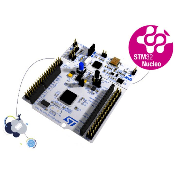
ST Nucleo F411RE
Overview
The Nucleo F411RE board features an ARM Cortex-M4 based STM32F411RE MCU with a wide range of connectivity support and configurations. Here are some highlights of the Nucleo F411RE board:
STM32 microcontroller in QFP64 package
Two types of extension resources:
Arduino Uno V3 connectivity
ST morpho extension pin headers for full access to all STM32 I/Os
On-board ST-LINK/V2-1 debugger/programmer with SWD connector
Flexible board power supply:
USB VBUS or external source(3.3V, 5V, 7 - 12V)
Power management access point
Three LEDs: USB communication (LD1), user LED (LD2), power LED (LD3)
Two push-buttons: USER and RESET
More information about the board can be found at the Nucleo F411RE website.
Hardware
Nucleo F411RE provides the following hardware components:
STM32F411RET6 in LQFP64 package
ARM® 32-bit Cortex®-M4 CPU with FPU
100 MHz max CPU frequency
VDD from 1.7 V to 3.6 V
512 KB Flash
128 KB SRAM
GPIO with external interrupt capability
12-bit ADC with 16 channels, with FIFO and burst support
RTC
8 General purpose timers
2 watchdog timers (independent and window)
SysTick timer
USART/UART (3)
I2C (3)
SPI/I2S (5)
SDIO
USB 2.0 OTG FS
DMA Controller
CRC calculation unit
More information about STM32F411RE can be found here:
Supported Features
The Zephyr nucleo_f411re board configuration supports the following hardware features:
Interface |
Controller |
Driver/Component |
|---|---|---|
NVIC |
on-chip |
nested vector interrupt controller |
UART |
on-chip |
serial port |
PINMUX |
on-chip |
pinmux |
GPIO |
on-chip |
gpio |
PWM |
on-chip |
pwm |
I2C |
on-chip |
i2c |
I2S |
on-chip |
i2s |
SPI |
on-chip |
spi |
Other hardware features are not yet supported on this Zephyr port.
The default configuration can be found in the defconfig file:
boards/arm/nucleo_f411re/nucleo_f411re_defconfig
Connections and IOs
Nucleo F411RE Board has 8 GPIO controllers. These controllers are responsible for pin muxing, input/output, pull-up, etc.
Available pins:
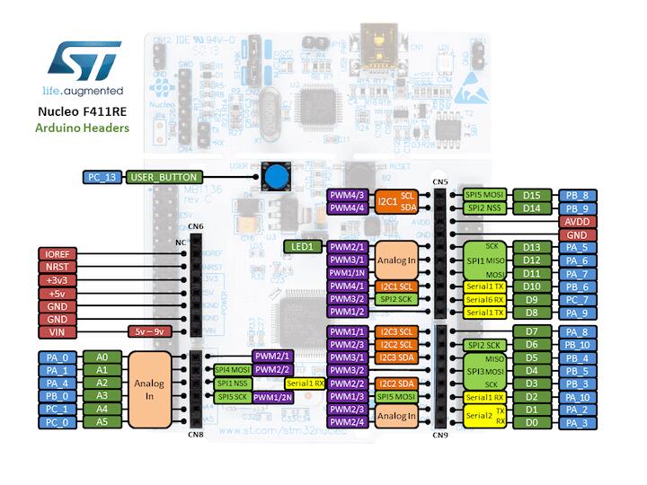
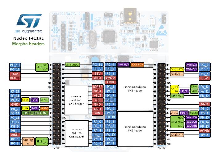
For more details please refer to STM32 Nucleo-64 board User Manual.
Default Zephyr Peripheral Mapping:
UART_1 TX/RX : PB6/PB7
UART_2 TX/RX : PA2/PA3 (ST-Link Virtual Port Com)
I2C1 SCL/SDA : PB8/PB9 (Arduino I2C)
I2C2 SCL/SDA : PB10/PB3
I2C1 SCL/SDA : PA8/B4
SPI1 CS/SCK/MISO/MOSI : PA4/PA5/PA6/PA7 (Arduino SPI)
I2S1 SCK/SD : PA5/PA7 (Arduino I2S)
USER_PB : PC13
LD2 : PA5
Note
Please note that SPI1 and I2S1 are connected to the same mcu pins, as the h/w controller is the same one.
System Clock
Nucleo F411RE System Clock could be driven by internal or external oscillator, as well as main PLL clock. By default System clock is driven by PLL clock at 84MHz, driven by 8MHz high speed external clock.
Serial Port
Nucleo F411RE board has 3 UARTs. The Zephyr console output is assigned to UART2. Default settings are 115200 8N1.
Programming and Debugging
Applications for the nucleo_f411re board configuration can be built and
flashed in the usual way (see Building an Application and
Run an Application for more details).
Flashing
Nucleo F411RE board includes an ST-LINK/V2-1 embedded debug tool interface. This interface is supported by the openocd version included in Zephyr SDK.
Flashing an application to Nucleo F411RE
Here is an example for the Hello World application.
Run a serial host program to connect with your Nucleo board.
$ minicom -D /dev/ttyACM0
Build and flash the application:
# From the root of the zephyr repository
west build -b nucleo_f411re samples/hello_world
west flash
You should see the following message on the console:
$ Hello World! arm
Debugging
You can debug an application in the usual way. Here is an example for the Hello World application.
# From the root of the zephyr repository
west build -b nucleo_f411re samples/hello_world
west debug