nRF5340 DK
Overview
The nRF5340 DK (PCA10095) is a single-board development kit for evaluation and development on the Nordic nRF5340 System-on-Chip (SoC).
The nRF5340 is a dual-core SoC based on the Arm® Cortex®-M33 architecture, with:
a full-featured Arm Cortex-M33F core with DSP instructions, FPU, and Armv8-M Security Extension, running at up to 128 MHz, referred to as the application core
a secondary Arm Cortex-M33 core, with a reduced feature set, running at a fixed 64 MHz, referred to as the network core.
The nrf5340dk_nrf5340_cpuapp build target provides support for the application core on the nRF5340 SoC. The nrf5340dk_nrf5340_cpunet build target provides support for the network core on the nRF5340 SoC.
nRF5340 SoC provides support for the following devices:
ADC
CLOCK
FLASH
GPIO
IDAU
I2C
MPU
NVIC
PWM
RADIO (Bluetooth Low Energy and 802.15.4)
RTC
Segger RTT (RTT Console)
SPI
UARTE
USB
WDT
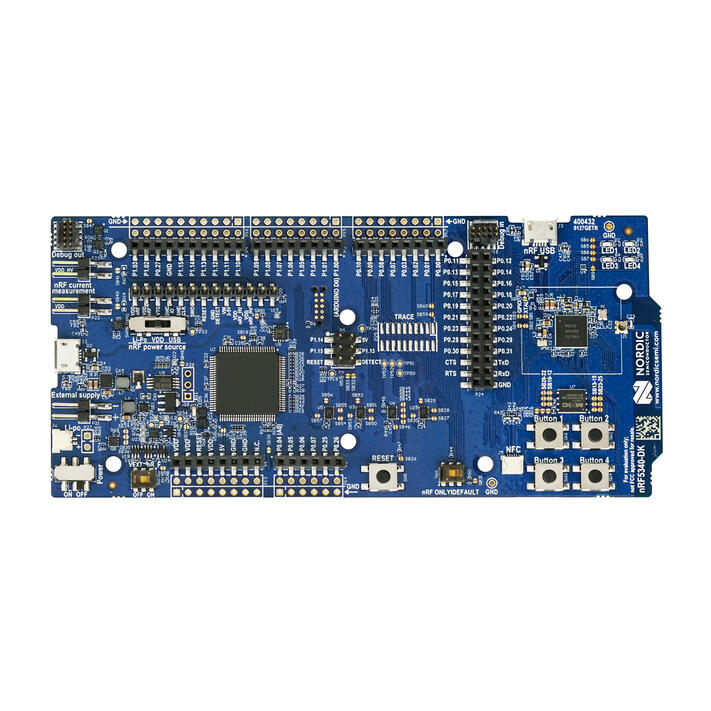
nRF5340 DK (Credit: Nordic Semiconductor)
More information about the board can be found at the nRF5340 DK website [2]. The Nordic Semiconductor Infocenter [3] contains the processor’s information and the datasheet.
Hardware
nRF5340 DK has two external oscillators. The frequency of the slow clock is 32.768 kHz. The frequency of the main clock is 32 MHz.
Supported Features
The nrf5340dk_nrf5340_cpuapp board configuration supports the following hardware features:
Interface |
Controller |
Driver/Component |
|---|---|---|
ADC |
on-chip |
adc |
CLOCK |
on-chip |
clock_control |
FLASH |
on-chip |
flash |
GPIO |
on-chip |
gpio |
I2C(M) |
on-chip |
i2c |
MPU |
on-chip |
arch/arm |
NVIC |
on-chip |
arch/arm |
PWM |
on-chip |
pwm |
RTC |
on-chip |
system clock |
RTT |
Segger |
console |
SPI(M/S) |
on-chip |
spi |
SPU |
on-chip |
system protection |
UARTE |
on-chip |
serial |
USB |
on-chip |
usb |
WDT |
on-chip |
watchdog |
The nrf5340dk_nrf5340_cpunet board configuration supports the following hardware features:
Interface |
Controller |
Driver/Component |
|---|---|---|
CLOCK |
on-chip |
clock_control |
FLASH |
on-chip |
flash |
GPIO |
on-chip |
gpio |
I2C(M) |
on-chip |
i2c |
MPU |
on-chip |
arch/arm |
NVIC |
on-chip |
arch/arm |
RADIO |
on-chip |
Bluetooth, ieee802154 |
RTC |
on-chip |
system clock |
RTT |
Segger |
console |
SPI(M/S) |
on-chip |
spi |
UARTE |
on-chip |
serial |
WDT |
on-chip |
watchdog |
Other hardware features have not been enabled yet for this board. See Nordic Semiconductor Infocenter [3] for a complete list of nRF5340 DK board hardware features.
Connections and IOs
LED
LED1 (green) = P0.28
LED2 (green) = P0.29
LED3 (green) = P0.30
LED4 (green) = P0.31
Security components
Implementation Defined Attribution Unit (IDAU [1]) on the application core. The IDAU is implemented with the System Protection Unit and is used to define secure and non-secure memory maps. By default, all of the memory space (Flash, SRAM, and peripheral address space) is defined to be secure accessible only.
Secure boot.
Programming and Debugging
nRF5340 application core supports the Armv8-M Security Extension. Applications built for the nrf5340dk_nrf5340_cpuapp board by default boot in the Secure state.
nRF5340 network core does not support the Armv8-M Security Extension. nRF5340 IDAU may configure bus accesses by the nRF5340 network core to have Secure attribute set; the latter allows to build and run Secure only applications on the nRF5340 SoC.
Building Secure/Non-Secure Zephyr applications with Arm® TrustZone®
Applications on the nRF5340 may contain a Secure and a Non-Secure firmware image for the application core. The Secure image can be built using either Zephyr or Trusted Firmware M [4] (TF-M). Non-Secure firmware images are always built using Zephyr. The two alternatives are described below.
Note
By default the Secure image for nRF5340 application core is built using TF-M.
Building the Secure firmware with TF-M
The process to build the Secure firmware image using TF-M and the Non-Secure firmware image using Zephyr requires the following steps:
Build the Non-Secure Zephyr application for the application core using
-DBOARD=nrf5340dk_nrf5340_cpuapp_ns. To invoke the building of TF-M the Zephyr build system requires the Kconfig optionBUILD_WITH_TFMto be enabled, which is done by default when building Zephyr as a Non-Secure application. The Zephyr build system will perform the following steps automatically:Build the Non-Secure firmware image as a regular Zephyr application
Build a TF-M (secure) firmware image
Merge the output image binaries together
Optionally build a bootloader image (MCUboot)
Note
Depending on the TF-M configuration, an application DTS overlay may be required, to adjust the Non-Secure image Flash and SRAM starting address and sizes.
Build the application firmware for the network core using
-DBOARD=nrf5340dk_nrf5340_cpunet.
Building the Secure firmware using Zephyr
The process to build the Secure and the Non-Secure firmware images using Zephyr requires the following steps:
Build the Secure Zephyr application for the application core using
-DBOARD=nrf5340dk_nrf5340_cpuappandCONFIG_TRUSTED_EXECUTION_SECURE=yandCONFIG_BUILD_WITH_TFM=nin the application project configuration file.Build the Non-Secure Zephyr application for the application core using
-DBOARD=nrf5340dk_nrf5340_cpuapp_ns.Merge the two binaries together.
Build the application firmware for the network core using
-DBOARD=nrf5340dk_nrf5340_cpunet.
When building a Secure/Non-Secure application for the nRF5340 application core, the Secure application will have to set the IDAU (SPU) configuration to allow Non-Secure access to all CPU resources utilized by the Non-Secure application firmware. SPU configuration shall take place before jumping to the Non-Secure application.
Building a Secure only application
Build the Zephyr app in the usual way (see Building an Application
and Run an Application), using -DBOARD=nrf5340dk_nrf5340_cpuapp for
the firmware running on the nRF5340 application core, and using
-DBOARD=nrf5340dk_nrf5340_cpunet for the firmware running
on the nRF5340 network core.
Flashing
Follow the instructions in the Nordic nRF5x Segger J-Link page to install and configure all the necessary software. Further information can be found in Flashing. Then you can build and flash applications as usual (Building an Application and Run an Application for more details).
Warning
The nRF5340 has a flash read-back protection feature. When flash read-back
protection is active, you will need to recover the chip before reflashing.
If you are flashing with west, run
this command for more details on the related --recover option:
west flash -H -r nrfjprog --skip-rebuild
Note
Flashing and debugging applications on the nRF5340 DK requires upgrading the nRF Command Line Tools to version 10.12.0. Further information on how to install the nRF Command Line Tools can be found in Flashing.
Here is an example for the Hello World application running on the nRF5340 application core.
First, run your favorite terminal program to listen for output.
$ minicom -D <tty_device> -b 115200
Replace <tty_device> with the port where the board nRF5340 DK
can be found. For example, under Linux, /dev/ttyACM0.
Then build and flash the application in the usual way.
# From the root of the zephyr repository
west build -b nrf5340dk_nrf5340_cpuapp samples/hello_world
west flash
Debugging
Refer to the Nordic nRF5x Segger J-Link page to learn about debugging Nordic boards with a Segger IC.