Adafruit ItsyBitsy M4 Express
Overview
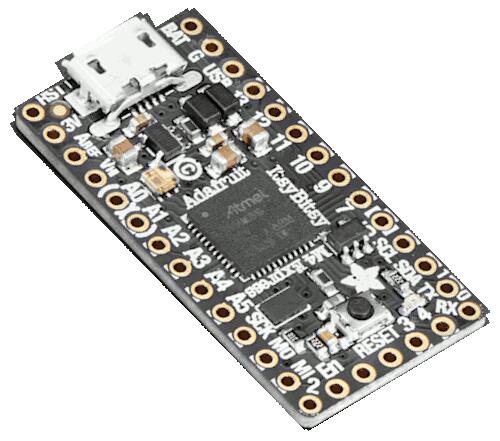
The Adafruit ItsyBitsy M4 express is a small (36 mm x 18 mm) ARM development board with an onboard RGB LED, USB port, 2 MiB of SPI flash, and range of I/O broken out onto 23 GPIO pins.
Hardware
ATSAMD51G19A ARM Cortex-M4 processor at 120 MHz
512 KiB of flash memory and 192 KiB of RAM
2 MiB of SPI flash
Internal trimmed 8 MHz oscillator
A user LED
An RGB DotStar LED
Native USB port
One reset button
Supported Features
The adafruit_itsybitsy_m4_express board configuration supports the following hardware features:
Interface |
Controller |
Driver/Component |
|---|---|---|
NVIC |
on-chip |
Nested vector interrupt controller |
SYSTICK |
on-chip |
systick |
WDT |
on-chip |
Watchdog |
GPIO |
on-chip |
I/O ports |
USART |
on-chip |
Serial ports |
SPI |
on-chip |
Serial Peripheral Interface ports |
TRNG |
on-chip |
True Random Number Generator |
HWINFO |
on-chip |
Unique 128 bit serial number |
RTC |
on-chip |
Real-Time Counter |
USB |
on-chip |
USB device |
WDT |
on-chip |
Watchdog Timer |
PWM |
on-chip |
PWM |
Other hardware features are not currently supported by Zephyr.
The default configuration can be found in the Kconfig file boards/arm/adafruit_itsybitsy_m4_express/adafruit_itsybitsy_m4_express_defconfig.
Zephyr can use the default Cortex-M SYSTICK timer or the SAM0 specific RTC.
To use the RTC, set CONFIG_CORTEX_M_SYSTICK=n and set
CONFIG_SYS_CLOCK_TICKS_PER_SEC to no more than 32 kHZ divided by 7,
i.e. no more than 4500.
Connections and IOs
The Adafruit Learning System [1] has detailed information about the board including pinouts [2] and the schematic [3].
System Clock
The SAMD51 MCU is configured to use the 32 kHz internal oscillator with the on-chip PLL generating the 120 MHz system clock.
Serial Port
The SAMD51 MCU has 6 SERCOM based USARTs. On the ItsyBitsy, SERCOM3 is the Zephyr console and is available on pins 0 (RX) and 1 (TX).
SPI Port
The SAMD51 MCU has 6 SERCOM based SPIs. On the ItsyBitsy, SERCOM1 can be put into SPI mode and used to connect to devices over the SCK (SCLK), MO (MOSI), and MI (MISO) pins.
PWM
The SAMD51 has three PWM generators with up to six channels each. TCC_0
has a resolution of 24 bits and all other generators are 16 bit. TCC_1
pin 2 is mapped to PA18 (D7) and pin 3 is mapped to PA19 (D9).
USB Device Port
The SAMD51 MCU has a USB device port that can be used to communicate with a host PC. See the USB device support samples sample applications for more, such as the USB CDC-ACM sample which sets up a virtual serial port that echos characters back to the host PC.
Programming and Debugging
The ItsyBitsy ships with a the BOSSA compatible UF2 bootloader. The bootloader can be entered by quickly tapping the reset button twice.
Additionally, if CONFIG_USB_CDC_ACM is enabled then the bootloader
will be entered automatically when you run west flash.
Flashing
Build the Zephyr kernel and the Hello World sample application:
west build -b adafruit_itsybitsy_m4_express samples/hello_world
Connect the ItsyBitsy to your host computer using USB
Connect a 3.3 V USB to serial adapter to the board and to the host. See the Serial Port section above for the board’s pin connections.
Run your favorite terminal program to listen for output. Under Linux the terminal should be
/dev/ttyUSB0. For example:$ minicom -D /dev/ttyUSB0 -o
The -o option tells minicom not to send the modem initialization string. Connection should be configured as follows:
Speed: 115200
Data: 8 bits
Parity: None
Stop bits: 1
Tap the reset button twice quickly to enter bootloader mode
Flash the image:
west build -b adafruit_itsybitsy_m4_express samples/hello_world
west flash
You should see “Hello World! adafruit_itsybitsy_m4_express” in your terminal.
Debugging
In addition to the built-in bootloader, the ItsyBitsy can be flashed and debugged using a SWD probe such as the Segger J-Link.
Connect the board to the probe by connecting the
SWCLK,SWDIO,RESET,GND, and3V3pins on the ItsyBitsy to theSWCLK,SWDIO,RESET,GND, andVTrefpins on the J-Link [4].Flash the image:
west build -b adafruit_itsybitsy_m4_express samples/hello_world
west flash -r openocd
Start debugging:
west build -b adafruit_itsybitsy_m4_express samples/hello_world
west debug