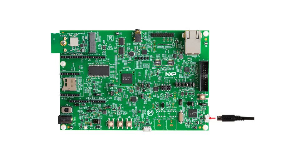
NXP MIMXRT1040-EVK
Overview
i.MX RT1040 crossover MCUs add additional flexibility with new packages and an extended temperature range up to 125° C. The i.MX RT1040 MCU has a compact 9x9 mm package, as well as the 11x11 mm package that supports implementing a 2-layer PCB design. The i.MX RT1040 MCUs run on the Arm® Cortex®-M7 core at 600 MHz.
Hardware
MIMXRT1042XJM5B MCU (600 MHz, 512 KB TCM)
Memory
256 MBit SDRAM (Winbond W9825G6KH)
64 Mbit QSPI Flash (Winbond W25Q64JVSSIQ)
Display
LCD connector
Touch connector
Ethernet
10/100 Mbit/s Ethernet PHY
USB
USB 2.0 OTG connector
Audio
3.5 mm audio stereo headphone jack
Board-mounted microphone
Power
5 V DC jack
Debug
JTAG 20-pin connector
OpenSDA with DAPLink
Expansion port
Arduino interface
CAN bus connector
For more information about the MIMXRT1040 SoC and MIMXRT1040-EVK board, see these references:
External Memory
This platform has the following external memories:
Device |
Controller |
Status |
|---|---|---|
W9825G6KH |
SEMC |
Enabled via device configuration data block, which sets up SEMC at boot time |
W25Q64JVSSIQ |
FLEXSPI |
Enabled via flash configurationn block, which sets up FLEXSPI at boot time. Supported for XIP only. |
Supported Features
The mimxrt1040_evk board configuration supports the hardware features listed below. For additional features not yet supported, please also refer to the NXP MIMXRT1064-EVK , which is the superset board in NXP’s i.MX RT10xx family. NXP prioritizes enabling the superset board with NXP’s Full Platform Support for Zephyr. Therefore, the mimxrt1064_evk board may have additional features already supported, which can also be re-used on this mimxrt1040_evk board:
Interface |
Controller |
Driver/Component |
|---|---|---|
NVIC |
on-chip |
nested vector interrupt controller |
SYSTICK |
on-chip |
systick |
GPIO |
on-chip |
gpio |
UART |
on-chip |
serial port-polling; serial port-interrupt |
PWM |
on-chip |
pwm |
ADC |
on-chip |
adc |
SPI |
on-chip |
spi |
DMA |
on-chip |
dma |
I2C |
on-chip |
i2c |
The default configuration can be found in the defconfig file:
boards/arm/mimxrt1040_evk/mimxrt1040_evk_defconfig
Other hardware features are not currently supported by the port.
Connections and IOs
The MIMXRT1040 SoC has five pairs of pinmux/gpio controllers.
Name |
Function |
Usage |
|---|---|---|
GPIO_AD_B0_12 |
LPUART1_TX |
UART Console |
GPIO_AD_B0_13 |
LPUART1_RX |
UART Console |
WAKEUP |
GPIO |
SW0 |
GPIO_AD_B0_08 |
GPIO |
User LD1 |
GPIO_AD_B0_10 |
FLEXPWM1 PWM3A |
PWM Output |
GPIO_AD_B0_14 |
ADC0 IN3 |
ADC0 Input |
GPIO_AD_B0_15 |
ADC0 IN4 |
ADC0 Input |
GPIO_SD_B0_02 |
LPSPI1_SDO |
SPI Output |
GPIO_SD_B0_03 |
LPSPI1_SDI |
SPI Input |
GPIO_SD_B0_00 |
LPSPI1_SCK |
SPI Clock |
GPIO_SD_B0_00 |
LPSPI1_SCK |
SPI Clock |
GPIO_AD_B1_00 |
LPI2C1_SCL |
I2C Clock |
GPIO_AD_B1_01 |
LPI2C1_SDA |
I2C Data |
Note
In order to use the SPI peripheral on this board, resistors R350, R346, and R360 must be populated with zero ohm resistors.
System Clock
The MIMXRT1040 SoC is configured to use SysTick as the system clock source, running at 600MHz.
When power management is enabled, the 32 KHz low frequency oscillator on the board will be used as a source for the GPT timer to generate a system clock. This clock enables lower power states, at the cost of reduced resolution
Serial Port
The MIMXRT1040 SoC has eight UARTs. LPUART1 is configured for the console,
and the remaining UARTs are not used.
Programming and Debugging
Build and flash applications as usual (see Building an Application and Run an Application for more details).
Configuring a Debug Probe
Programming and Debugging
Build and flash applications as usual (see Building an Application and Run an Application for more details).
Configuring a Debug Probe
A debug probe is used for both flashing and debugging the board. This board is configured by default to use the OpenSDA DAPLink Onboard Debug Probe, however the pyOCD Debug Host Tools do not yet support programming the external flashes on this board so you must reconfigure the board for one of the following debug probes instead.
Option 1: OpenSDA J-Link Onboard Debug Probe (Recommended)
Install the J-Link Debug Host Tools and make sure they are in your search path.
Check that jumpers J9 and J10 are on to ensure SWD signals are connected to the OpenSDA microcontroller. Then, follow the instructions in NXP AN13206 to program a JLink based firmware to the LPC4322 based debugger on this board.
Once the JLink based firmware is present on this board, the SOC will no longer be powered via the USB connection to J1. Move J40 to short pins 3 and 4 in order to use J48 for USB power, and connect another USB cable to power the SoC. LED D16 should illuminate to indicate the board is powered, and it should now be possible to program the SoC.
Option 2: J-Link External Debug Probe
Install the J-Link Debug Host Tools and make sure they are in your search path.
The board can be programmed using the J-Link External Debug Probe, provided the onboard debug circuit’s SWD signals are isolated from the MCU. To do so, ensure that jumpers J9 and J10 are off (they are on by default when the board ships from the factory). The external probe’s 20 pin connector can then be connected to J2 to program the SOC.
Configuring a Console
Regardless of your choice in debug probe, we will use the OpenSDA microcontroller as a usb-to-serial adapter for the serial console. Check that jumpers J11 and J13 are on (they are on by default when boards ship from the factory) to connect UART signals to the OpenSDA microcontroller.
Connect a USB cable from your PC to J1.
Use the following settings with your serial terminal of choice (minicom, putty, etc.):
Speed: 115200
Data: 8 bits
Parity: None
Stop bits: 1
Flashing
Here is an example for the Hello World application.
# From the root of the zephyr repository
west build -b mimxrt1040_evk samples/hello_world
west flash
Open a serial terminal, reset the board (press the SW1 button), and you should see the following message in the terminal:
***** Booting Zephyr OS Booting Zephyr OS build v3.3.0-rc3-66 *****
Hello World! mimxrt1040_evk
Debugging
Here is an example for the Hello World application.
# From the root of the zephyr repository
west build -b mimxrt1040_evk samples/hello_world
west debug
Open a serial terminal, step through the application in your debugger, and you should see the following message in the terminal:
***** Booting Zephyr OS Booting Zephyr OS build v3.3.0-rc3-66 *****
Hello World! mimxrt1040_evk
Troubleshooting
USER_LED D8
The MIMXRT1040-EVK board ships with the wireless module in the M.2 connector, and with jumper J80 shorted. This causes a conflict with the USER_LED D8, and the LED will not turn off. Samples and applications using USER_LED D8, like blinky, require removal of J80 jumper.
Boot Header
If the debug probe fails to connect with the following error, it’s possible
that the boot header in QSPI is invalid or corrupted. The boot header is
configured by CONFIG_NXP_IMX_RT_BOOT_HEADER.
Remote debugging using :2331
Remote communication error.  Target disconnected.: Connection reset by peer.
"monitor" command not supported by this target.
"monitor" command not supported by this target.
You can't do that when your target is `exec'
(gdb) Could not connect to target.
Please check power, connection and settings.
You can fix it by erasing and reprogramming the QSPI with the following steps:
Set the SW4 DIP switches to OFF-OFF-OFF-ON to boot into the ROM bootloader.
Reset by pressing SW1
Run
west debugorwest flashagain with a known working Zephyr application.Set the SW4 DIP switches to OFF-OFF-ON-OFF to boot from QSPI.
Reset by pressing SW1
WiFi Module
If the debugger fails to connect with the following error, it’s possible the M.2 WiFi module is interfering with the debug signals
Remote debugging using :2331
Remote communication error.  Target disconnected.: Connection reset by peer.
"monitor" command not supported by this target.
"monitor" command not supported by this target.
You can't do that when your target is `exec'
(gdb) Could not connect to target.
Please check power, connection and settings.
To resolve this, you may remove the M.2 WiFi module from the board when flashing or debugging it, or remove jumper J80.