ST STM32L562E-DK Discovery
Overview
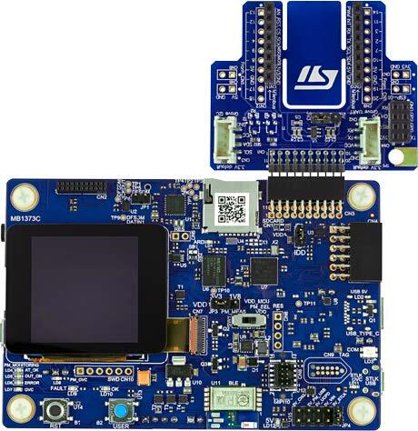
The STM32L562E-DK Discovery kit is designed as a complete demonstration and development platform for STMicroelectronics Arm® Cortex®-M33 core-based STM32L562QEI6QU microcontroller with TrustZone®. Here are some highlights of the STM32L562E-DK Discovery board:
STM32L562QEI6QU microcontroller featuring 512 Kbytes of Flash memory and 256 Kbytes of SRAM in BGA132 package
1.54” 240 x 240 pixel-262K color TFT LCD module with parallel interface and touch-control panel
USB Type-C™ Sink device FS
On-board energy meter: 300 nA to 150 mA measurement range with a dedicated USB interface
SAI Audio CODEC
MEMS digital microphones
512-Mbit Octal-SPI Flash memory
Bluetooth® V4.1 Low Energy module
iNEMO 3D accelerometer and 3D gyroscope
Board connectors
STMod+ expansion connector with fan-out expansion board for Wi‑Fi®, Grove and mikroBUS™ compatible connectors
Pmod™ expansion connector
Audio MEMS daughterboard expansion connector
ARDUINO® Uno V3 expansion connector
Flexible power-supply options
ST-LINK
USB VBUS
external sources
On-board STLINK-V3E debugger/programmer with USB re-enumeration capability:
mass storage
Virtual COM port
debug port
2 user LEDs
User and reset push-buttons
More information about the board can be found at the STM32L562E-DK Discovery website.
Hardware
The STM32L562xx devices are an ultra-low-power microcontrollers family (STM32L5 Series) based on the high-performance Arm® Cortex®-M33 32-bit RISC core. They operate at a frequency of up to 110 MHz.
Ultra-low-power with FlexPowerControl (down to 108 nA Standby mode and 62 uA/MHz run mode)
Core: ARM® 32-bit Cortex® -M33 CPU with TrustZone® and FPU.
Performance benchmark:
1.5 DMPIS/MHz (Drystone 2.1)
442 CoreMark® (4.02 CoreMark® /MHZ)
Security
Arm® TrustZone® and securable I/Os memories and peripherals
Flexible life cycle scheme with RDP (readout protection)
Root of trust thanks to unique boot entry and hide protection area (HDP)
Secure Firmware Installation thanks to embedded Root Secure Services
Secure Firmware Update support with TF-M
AES coprocessor
Public key accelerator
On-the-fly decryption of Octo-SPI external memories
HASH hardware accelerator
Active tamper and protection temperature, voltage and frequency attacks
True Random Number Generator NIST SP800-90B compliant
96-bit unique ID
512-byte One-Time Programmable for user data
Clock management:
4 to 48 MHz crystal oscillator
32 kHz crystal oscillator for RTC (LSE)
Internal 16 MHz factory-trimmed RC ( ±1%)
Internal low-power 32 kHz RC ( ±5%)
Internal multispeed 100 kHz to 48 MHz oscillator, auto-trimmed by LSE (better than ±0.25 % accuracy)
3 PLLs for system clock, USB, audio, ADC
Power management
Embedded regulator (LDO) with three configurable range output to supply the digital circuitry
Embedded SMPS step-down converter
External SMPS support
RTC with HW calendar, alarms and calibration
Up to 114 fast I/Os, most 5 V-tolerant, up to 14 I/Os with independent supply down to 1.08 V
Up to 22 capacitive sensing channels: support touchkey, linear and rotary touch sensors
Up to 16 timers and 2 watchdogs
2x 16-bit advanced motor-control
2x 32-bit and 5x 16-bit general purpose
2x 16-bit basic
3x low-power 16-bit timers (available in Stop mode)
2x watchdogs
2x SysTick timer
Memories
Up to 512 MB Flash, 2 banks read-while-write
512 KB of SRAM including 64 KB with hardware parity check
External memory interface for static memories supporting SRAM, PSRAM, NOR, NAND and FRAM memories
OCTOSPI memory interface
Rich analog peripherals (independent supply)
3x 12-bit ADC 5 MSPS, up to 16-bit with hardware oversampling, 200 uA/MSPS
2x 12-bit DAC, low-power sample and hold
2x operational amplifiers with built-in PGA
2x ultra-low-power comparators
4x digital filters for sigma delta modulator
19x communication interfaces
USB Type-C / USB power delivery controller
2.0 full-speed crystal less solution, LPM and BCD
2x SAIs (serial audio interface)
4x I2C FM+(1 Mbit/s), SMBus/PMBus
6x USARTs (ISO 7816, LIN, IrDA, modem)
3x SPIs (7x SPIs with USART and OCTOSPI in SPI mode)
1xFDCAN
1xSDMMC interface
2x 14 channel DMA controllers
CRC calculation unit
Development support: serial wire debug (SWD), JTAG, Embedded Trace Macrocell™
More information about STM32L562QE can be found here:
Supported Features
The Zephyr stm32l562e_dk board configuration supports the following hardware features:
Interface |
Controller |
Driver/Component |
|---|---|---|
ADC |
on-chip |
ADC Controller |
AES |
on-chip |
crypto |
CLOCK |
on-chip |
reset and clock control |
DAC |
on-chip |
DAC Controller |
DMA |
on-chip |
Direct Memory Access |
GPIO |
on-chip |
gpio |
I2C |
on-chip |
i2c |
NVIC |
on-chip |
nested vector interrupt controller |
PINMUX |
on-chip |
pinmux |
PWM |
on-chip |
PWM |
RNG |
on-chip |
entropy |
SDMMC |
on-chip |
sd/mmc |
SPI |
on-chip |
spi |
TrustZone |
on-chip |
Trusted Firmware-M |
UART |
on-chip |
serial port-polling; serial port-interrupt |
WATCHDOG |
on-chip |
independent watchdog |
USB |
on-chip |
usb |
Other hardware features are not yet supported on this Zephyr port.
The default configuration can be found in the defconfig and dts files:
Zephyr board options
The STM32L562e is an SoC with Cortex-M33 architecture. Zephyr provides support for building for both Secure and Non-Secure firmware.
The BOARD options are summarized below:
BOARD |
Description |
|---|---|
stm32l562e_dk |
For building Secure (or Secure-only) firmware |
stm32l562e_dk_ns |
For building Non-Secure firmware |
Here are the instructions to build Zephyr with a non-secure configuration, using tfm_ipc_ sample:
$ west build -b stm32l562e_dk_ns samples/tfm_integration/tfm_ipc/
Once done, before flashing, you need to first run a generated script that will set platform option bytes config and erase platform (among others, option bit TZEN will be set).
$ ./build/tfm/regression.sh
$ west flash
Please note that, after having run a TFM sample on the board, you will need to run ./build/tfm/regression.sh once more to clean up the board from secure options and get back the platform back to a “normal” state and be able to run usual, non-TFM, binaries. Also note that, even then, TZEN will remain set, and you will need to use STM32CubeProgrammer to disable it fully, if required.
Connections and IOs
STM32L562E-DK Discovery Board has 8 GPIO controllers. These controllers are responsible for pin muxing, input/output, pull-up, etc.
For more details please refer to STM32L562E-DK Discovery board User Manual.
Default Zephyr Peripheral Mapping:
USART_1 TX/RX : PA9/PA10
USART_3 TX/RX : PC10/PC11
I2C_1 SCL/SDA : PB6/PB7
SPI_1 SCK/MISO/MOSI : PG2/PG3/PG4 (BT SPI bus)
SPI_3 NSS/SCK/MISO/MOSI : PE0/PG9/PB4/PB5 (Arduino SPI)
USER_PB : PC13
LD10 : PG12
PWM_2_CH1 : PA0
DAC1 : PA4
ADC1 : PC4
System Clock
STM32L562E-DK System Clock could be driven by internal or external oscillator, as well as main PLL clock. By default System clock is driven by PLL clock at 110MHz, driven by 4MHz medium speed internal oscillator.
Serial Port
STM32L562E-DK Discovery board has 6 U(S)ARTs. The Zephyr console output is assigned to USART1. Default settings are 115200 8N1.
Programming and Debugging
Applications for the stm32l562e_dk board configuration can be built and
flashed in the usual way (see Building an Application and
Run an Application for more details).
Flashing
STM32L562E-DK Discovery board includes an ST-LINK/V3E embedded debug tool interface. Support can be enabled on pyocd by adding “pack” support with the following pyocd command:
$ pyocd pack --update
$ pyocd pack --install stm32l562qe
Alternatively, this interface is supported by the openocd version included in the Zephyr SDK since v0.13.1.
Flashing an application to STM32L562E-DK Discovery
Connect the STM32L562E-DK Discovery to your host computer using the USB port. Then build and flash an application. Here is an example for the Hello World application.
Run a serial host program to connect with your Nucleo board:
$ minicom -D /dev/ttyACM0
Then build and flash the application.
# From the root of the zephyr repository
west build -b stm32l562e_dk samples/hello_world
west flash
You should see the following message on the console:
Hello World! stm32l562e_dk
Building Secure/Non-Secure Zephyr applications with Arm® TrustZone®
The TF-M integration sample TF-M IPC can be run on a ST STM32L562E-DK Discovery.
In TF-M configuration, Zephyr is run on the non-secure domain. A non-secure image
can be generated using stm32l562e_dk_ns as build target.
$ west build -b stm32l562e_dk_ns path/to/source/directory
Note: When building the *_ns image with TF-M, build/tfm/api_ns/postbuild.sh bash script
is run automatically in a post-build step to make some required flash layout changes.
Once the build is completed, run the following script to initialize the option bytes.
$ build/tfm/regression.sh
Finally, to flash the board, run:
$ west flash --hex-file build/tfm_merged.hex
Note: Check the build/tfm directory to ensure that the commands required by these scripts
(readlink, etc.) are available on your system. Please also check STM32_Programmer_CLI
(which is used for initialization) is available in the PATH.
Debugging
You can debug an application in the usual way. Here is an example for the Hello World application.
# From the root of the zephyr repository
west build -b stm32l562e_dk samples/hello_world
west debug