SAM L21 Xplained Pro Evaluation Kit
Overview
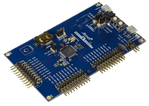
The SAM L21 Xplained Pro evaluation kit is ideal for evaluation and prototyping with the SAM L21 Cortex®-M0+ processor-based microcontrollers. The kit includes Atmel’s Embedded Debugger (EDBG), which provides a full debug interface without the need for additional hardware.
Hardware
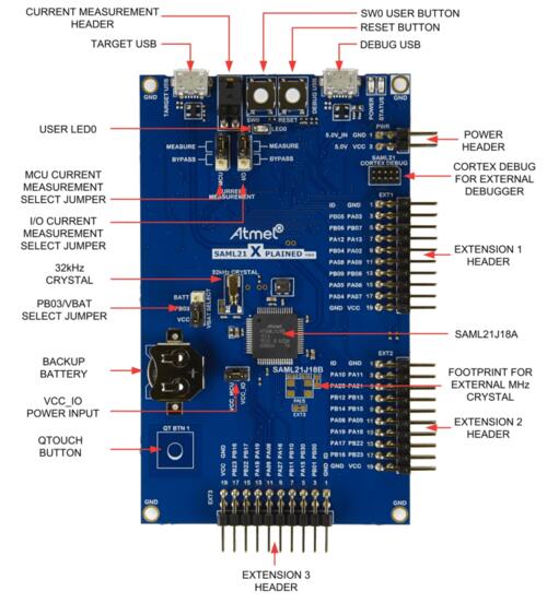
ATSAML21J18 ARM Cortex-M0+ processor at 48 MHz
32.768 kHz crystal oscillator
256 KiB flash memory, 32 KiB of SRAM, 8KB Low Power SRAM
One yellow user LED
One mechanical user push button
One reset button
On-board USB based EDBG unit with serial console
Supported Features
The atsaml21_xpro board configuration supports the following hardware features:
Interface |
Controller |
Driver / Component |
|---|---|---|
NVIC |
on-chip |
nested vector interrupt controller |
Flash |
on-chip |
Can be used with LittleFS to store files |
SYSTICK |
on-chip |
systick |
WDT |
on-chip |
Watchdog |
GPIO |
on-chip |
I/O ports |
PWM |
on-chip |
Pulse Width Modulation |
USART |
on-chip |
Serial ports |
I2C |
on-chip |
I2C ports |
SPI |
on-chip |
Serial Peripheral Interface ports |
TRNG |
on-chip |
True Random Number Generator |
Other hardware features are not currently supported by Zephyr.
The default configuration can be found in the Kconfig
boards/arm/atsaml21_xpro/atsaml21_xpro_defconfig.
Pin Mapping
The SAM L21 Xplained Pro evaluation kit has 2 GPIO controllers. These controllers are responsible for pin muxing, input/output, pull-up, etc.
For more details please refer to SAM L21 Family Datasheet [1] and the SAM L21 Xplained Pro Schematic [2].
Default Zephyr Peripheral Mapping:
SERCOM0 SPI MISO : PA04
SERCOM0 SPI MOSI : PA06
SERCOM0 SPI SCK : PA07
SERCOM1 USART TX : PA18
SERCOM1 USART RX : PA19
SERCOM2 I2C SDA : PA08
SERCOM2 I2C SCL : PA09
SERCOM3 USART TX : PA22
SERCOM3 USART RX : PA23
SERCOM4 USART TX : PB08
SERCOM4 USART RX : PB09
SERCOM5 SPI MISO : PB16
SERCOM5 SPI MOSI : PB22
SERCOM5 SPI SCK : PB23
USB DP : PA25
USB DM : PA24
GPIO SPI CS : PB17
GPIO/PWM LED0 : PB10
System Clock
The SAML21 MCU is configured to use the 32.768 kHz external oscillator with the on-chip PLL generating the 48 MHz system clock.
Serial Port
The SAML21 MCU has six SERCOM based USARTs with two configured as USARTs in this BSP. SERCOM3 is the default Zephyr console.
SERCOM1 115200 8n1 - connected to EXT2 and EXT3
SERCOM3 115200 8n1 - connected to the onboard Atmel Embedded Debugger (EDBG)
SERCOM4 115200 8n1 - connected to EXT1
PWM
The SAML21 MCU has 3 TCC based PWM units with up to 4 outputs each and a period
of 24 bits or 16 bits. If CONFIG_PWM_SAM0_TCC is enabled then LED0 is
driven by TCC0 instead of by GPIO.
SPI Port
The SAML21 MCU has 6 SERCOM based SPIs, with two configured as SPI in this BSP.
SERCOM0 - connected to EXT1
SERCOM5 - connected to EXT2 and EXT3
Programming and Debugging
The SAM L21 Xplained Pro comes with a Atmel Embedded Debugger (EDBG). This provides a debug interface to the SAML21 chip and is supported by OpenOCD.
Flashing
Build the Zephyr kernel and the
hello_worldsample application:west build -b atsaml21_xpro samples/hello_world
Connect the SAM L21 Xplained Pro to your host computer using the USB debug port.
Run your favorite terminal program to listen for output. Under Linux the terminal should be
/dev/ttyACM0. For example:$ picocom -b 115200 /dev/ttyACM0
Speed: 115200
Data: 8 bits
Parity: None
Stop bits: 1
To flash an image:
west build -b atsaml21_xpro samples/hello_world
west flash
You should see “Hello World! atsaml21_xpro” in your terminal.