ST STM32 Flight Controller Unit
Overview
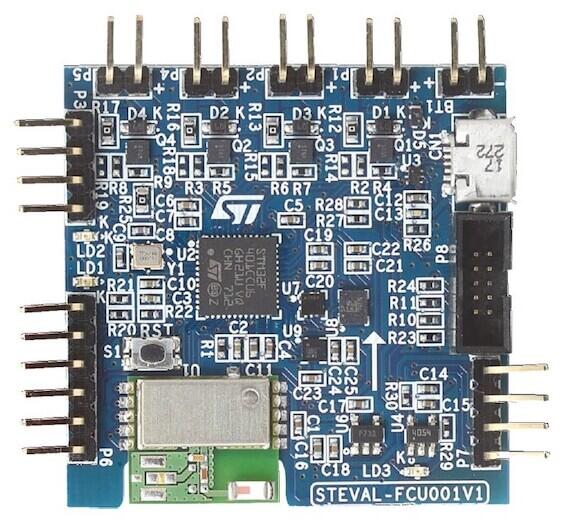
The STEVAL-FCU001V1 is a Cortex M4 MCU-based flight controller unit for toy quad-copter drones.
Hardware
STM32 Flight Controller Unit provides the following hardware components:
STM32F401CC in UFQFPN48 package
ARM® 32-bit Cortex®-M4 MCU with FPU
84MHz max MCU frequency
VDD from 1.7 V to 3.6 V
256 KB FLASH
64 KB SRAM
General Purpose Timers
Watchdog Timers (2)
On board sensors:
3D Accelerometer and 3D Gyroscope: LSM6DSL
3D Magnetometer: LIS2MDL
MEMS Pressure sensor: LPS22HD
2 User LEDS
USART/UART (1)
I2C (1)
Bluetooth LE over SPI
More information about the STM32 Flight Controller Unit can be found in these documents:
Supported Features
The Zephyr steval_fcu001v1 board configuration supports the following hardware features:
Interface |
Controller |
Driver/Component |
|---|---|---|
NVIC |
on-chip |
nested vector interrupt controller |
UART |
on-chip |
serial port-polling; serial port-interrupt |
PINMUX |
on-chip |
pinmux |
GPIO |
on-chip |
gpio |
PWM |
on-chip |
pwm |
I2C |
on-chip |
i2c |
The default configuration can be found in the defconfig file:
boards/arm/steval_fcu001v1/steval_fcu001v1_defconfig
Default Zephyr Peripheral Mapping:
UART_1 TX/RX : PA9/PA10
I2C2 SCL/SDA : PB10/PB3
PWM_2_CH1 : PA0
LD1 : PB5
LD2 : PB4
System Clock
The steval_fcu001v1 system clock can be driven by an internal or external oscillator, as well as by the main PLL clock. By default, the system clock is driven by the PLL clock at 84MHz, driven by a 16MHz high-speed external clock.
Serial Port
The steval_fcu001v1 board has one UART. The Zephyr console output is assigned to UART1. Default settings are 115200 8N1.
I2C
The steval_fcu001v1 board has one I2C. The default I2C mapping for Zephyr is:
I2C2_SCL : PB10
I2C2_SDA : PB3
Programming and Debugging
Applications for the steval_fcu001v1 board configuration can be built and
flashed in the usual way (see Building an Application and
Run an Application for more details).
Flashing
Flashing Zephyr onto the steval_fcu001v1 board requires an external ST-LINK/V2-1 programmer. The programmer is attached to the P8 programming header with ARM-JTAG-20-10-Plug-in Adapter.
Flashing an application to STEVAL_FCU001V1
Connect the FT232-to-USB port to host system, and RX, TX, Gnd pins to the P7 header of the steval_fcu001v1 board. Then run a serial host program to connect with your steval_fcu001v1 via the FT232 board:
$ minicom -D /dev/ttyUSB0
Now build and flash an application. Here is an example for Hello World
# From the root of the zephyr repository
west build -b steval_fcu001v1 samples/hello_world
west flash
You should see the following message on the console:
Hello World! steval_fcu001v1
Debugging
You can debug an application in the usual way. Here is an example for the Hello World application.
# From the root of the zephyr repository
west build -b steval_fcu001v1 samples/hello_world
west debug