NXP FRDM-K22F
Overview
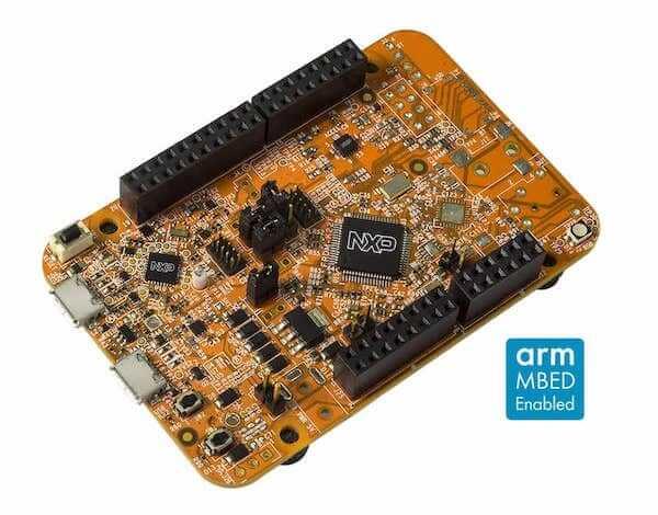
The Freedom-K22F is an ultra-low-cost development platform for Kinetis K22 MCUs.
Form-factor compatible with the Arduino R3 pin layout
Peripherals enable rapid prototyping, including a 6-axis digital accelerometer and magnetometer to create full eCompass capabilities, a tri-colored LED and 2 user push-buttons for direct interaction, a optional microSD card slot, and headers for use with Bluetooth* and 2.4 GHz radio add-on modules
OpenSDAv2, the NXP open source hardware embedded serial and debug adapter running an open source bootloader, offers options for serial communication, flash programming, and run-control debugging
Hardware
MK22FN512VLH12 (120 MHz, 1 MB flash memory, 256 KB RAM, low-power, crystal-less USB, and 64 pin Low profile Quad Flat Package (LQFP))
Dual role USB interface with micro-B USB connector
RGB LED
FXOS8700CQ accelerometer and magnetometer
Two user push buttons
Flexible power supply option - OpenSDAv2 USB, Kinetis K22 USB, and external source
Easy access to MCU input/output through Arduino* R3 compatible I/O connectors
Programmable OpenSDAv2 debug circuit supporting the CMSIS-DAP Interface software that provides:
Mass storage device (MSD) flash programming interface
CMSIS-DAP debug interface over a driver-less USB HID connection providing run-control debugging and compatibility with IDE tools
Virtual serial port interface
Open source CMSIS-DAP software project
Optional SDHC
For more information about the K22F SoC and FRDM-K22F board:
Supported Features
The frdm_k22f board configuration supports the hardware features listed below. For additional features not yet supported, please also refer to the NXP FRDM-K64F, which is the superset board in NXP’s Kinetis K series. NXP prioritizes enabling the superset board with NXP’s Full Platform Support for Zephyr. Therefore, the frdm_k64f board may have additional features already supported, which can also be re-used on this frdm_k22f board:
Interface |
Controller |
Driver/Component |
|---|---|---|
NVIC |
on-chip |
nested vector interrupt controller |
SYSTICK |
on-chip |
systick |
PINMUX |
on-chip |
pinmux |
GPIO |
on-chip |
gpio |
I2C |
on-chip |
i2c |
SPI |
on-chip |
spi |
WATCHDOG |
on-chip |
watchdog |
ADC |
on-chip |
adc |
PWM |
on-chip |
pwm |
UART |
on-chip |
serial port-polling; serial port-interrupt |
FLASH |
on-chip |
soc flash |
USB |
on-chip |
USB device |
SENSOR |
off-chip |
fxos8700 polling; fxos8700 trigger |
RNGA |
on-chip |
entropy; random |
FTFE |
on-chip |
flash programming |
The default configuration can be found in the defconfig file:
boards/arm/frdm_k22f/frdm_k22f_defconfig
Other hardware features are not currently supported by the port.
Connections and IOs
The K22F SoC has five pairs of pinmux/gpio controllers.
Name |
Function |
Usage |
|---|---|---|
PTA1 |
GPIO |
Red LED |
PTA2 |
GPIO |
Green LED |
PTD5 |
GPIO |
Blue LED |
PTC1 |
GPIO |
SW2 |
PTD0 |
GPIO |
FXOS8700 INT1 |
PTD1 |
GPIO |
FXOS8700 INT2 |
PTB17 |
GPIO |
SW3 |
PTE1 |
UART1_RX |
UART Console |
PTE0 |
UART1_TX |
UART Console |
PTD2 |
UART2_RX |
UART BT HCI |
PTD3 |
UART2_TX |
UART BT HCI |
PTC4 |
SPI0_PCS0 |
SPI |
PTD1 |
SPI0_SCK |
SPI |
PTD2 |
SPI0_SOUT |
SPI |
PTD3 |
SPI0_SIN |
SPI |
PTB2 |
I2C0_SCL |
I2C / FXOS8700 |
PTB3 |
I2C0_SDA |
I2C / FXOS8700 |
System Clock
The K22F SoC is configured to use the 8 MHz crystal oscillator on the board with the on-chip PLL to generate a 72 MHz system clock in its RUN mode. This clock was selected to allow for the maximum number of peripherals to be used with the crystal and PLL clocks. Other clock configurations are possible through NXP SDK currently.
Serial Port
The K22F SoC has three UARTs. One is configured for the console, another for BT HCI, and the remaining are not used.
USB
The K22F SoC has a USB OTG (USBOTG) controller that supports both device and host functions through its micro USB connector (K22F USB). Only USB device function is supported in Zephyr at the moment.
Programming and Debugging
Build and flash applications as usual (see Building an Application and Run an Application for more details).
Configuring a Debug Probe
A debug probe is used for both flashing and debugging the board. This board is configured by default to use the OpenSDA DAPLink Onboard Debug Probe.
Early versions of this board have an outdated version of the OpenSDA bootloader and require an update. Please see the DAPLink Bootloader Update page for instructions to update from the CMSIS-DAP bootloader to the DAPLink bootloader.
Option 1: OpenSDA DAPLink Onboard Debug Probe (Recommended)
Install the pyOCD Debug Host Tools and make sure they are in your search path.
Follow the instructions in OpenSDA DAPLink Onboard Debug Probe to program the OpenSDA DAPLink FRDM-K22F Firmware.
Option 2: OpenSDA J-Link Onboard Debug Probe
Install the J-Link Debug Host Tools and make sure they are in your search path.
Follow the instructions in OpenSDA J-Link Onboard Debug Probe to program the Segger J-Link OpenSDA V2.1 Firmware. Note that Segger does provide an OpenSDA J-Link Board-Specific Firmware for this board, however it is not compatible with the DAPLink bootloader.
Add the arguments -DBOARD_FLASH_RUNNER=jlink and
-DBOARD_DEBUG_RUNNER=jlink when you invoke west build to override the
default runner from pyOCD to J-Link:
# From the root of the zephyr repository
west build -b frdm_k22f samples/hello_world -- -DBOARD_FLASH_RUNNER=jlink -DBOARD_DEBUG_RUNNER=jlink
Configuring a Console
Regardless of your choice in debug probe, we will use the OpenSDA microcontroller as a usb-to-serial adapter for the serial console.
Connect a USB cable from your PC to J26.
Use the following settings with your serial terminal of choice (minicom, putty, etc.):
Speed: 115200
Data: 8 bits
Parity: None
Stop bits: 1
Flashing
Here is an example for the Hello World application.
# From the root of the zephyr repository
west build -b frdm_k22f samples/hello_world
west flash
Open a serial terminal, reset the board (press the SW1 button), and you should see the following message in the terminal:
***** Booting Zephyr OS v2.0.0 *****
Hello World! frdm_k22f
Debugging
Here is an example for the Hello World application.
# From the root of the zephyr repository
west build -b frdm_k22f samples/hello_world
west debug
Open a serial terminal, step through the application in your debugger, and you should see the following message in the terminal:
***** Booting Zephyr OS v2.0.0 *****
Hello World! frdm_k22f