ST B-G474E-DPOW1 Discovery
Overview
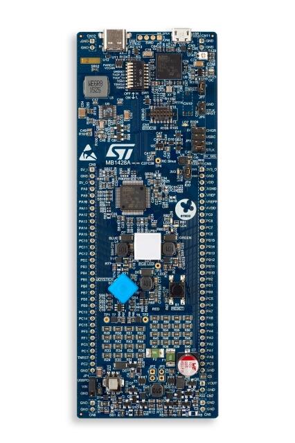
The B-G474E-DPOW1 Discovery kit is a digital power solution and a complete demonstration and development platform for the STMicroelectronics STM32G474RET6 microcontroller. Leveraging the new HRTimer-oriented features, 96 Kbytes of embedded RAM, math accelerator functions and USB-PD 3.0 offered by STM32G474RET6, the B-G474E-DPOW1 Discovery kit, based on the USB 2.0 FS Type-C™ connector interface, helps the user to prototype applications with digital power such as a buck-boost converter, RGB power LED lighting or a class-D audio amplifier. The B-G474E-DPOW1 Discovery kit does not require any separate probe, as it integrates the STLINK-V3E debugger and programmer.
STM32G474RET6 Arm® Cortex®-M4 core-based microcontroller, featuring 512 Kbytes of Flash memory and 128 Kbytes of SRAM, in LQFP64 package
USB Type-C™ with USB 2.0 FS interface compatible with USB-PD 3.0
RGB power LED for a bright lighting
Digital power buck-boost converter with internal or external Input voltage and with onboard resistor loads
Audio Class-D amplifier capable
4 user LEDs
3 LEDs for power and ST-LINK communication
4-direction joystick with a selection button
Reset push-button
- Board connectors:
USB Type-C™
USB Micro-B
2 x 32-pin header, 2.54 mm pitch, daughterboard extension connector for breadboard connection
Flexible power-supply options: ST-LINK USB VBUS or USB Type-C™ VBUS or external source
On-board STLINK-V3E debugger/programmer with USB re-enumeration capability: mass storage, Virtual COM port, and debug port
More information about the board can be found at the B-G474E-DPOW1 website [1].
More information about STM32G474RE can be found here: - G474RE on www.st.com [4] - STM32G4 reference manual [2]
Supported Features
The Zephyr b_g474e_dpow1 board configuration supports the following hardware features:
Interface |
Controller |
Driver/Component |
|---|---|---|
NVIC |
on-chip |
nested vector interrupt controller |
UART |
on-chip |
serial port-polling; serial port-interrupt |
GPIO |
on-chip |
gpio |
USB |
on-chip |
usb |
UCPD |
on-chip |
ucpd |
WATCHDOG |
on-chip |
independent watchdog |
Other hardware features are not yet supported in this Zephyr port.
The default configuration can be found in the defconfig file:
boards/arm/b_g474e_dpow1/b_g474e_dpow1_defconfig
Connections and IOs
Each of the GPIO pins can be configured by software as output (push-pull or open-drain), as input (with or without pull-up or pull-down), or as peripheral alternate function. Most of the GPIO pins are shared with digital or analog alternate functions. All GPIOs are high current capable except for analog inputs.
Default Zephyr Peripheral Mapping:
UART_3 TX/RX : PC10/PC11 (ST-Link Virtual Port Com)
BUTTON (JOY_SEL) : PC13
BUTTON (JOY_LEFT) : PC4
BUTTON (JOY_DOWN) : PC5
BUTTON (JOY_RIGHT) : PB2
BUTTON (JOY_UP) : PB10
LED (DOWN BLUE) : PA15
LED (LEFT ORANGE) : PB1
LED (UP RED) : PB5
LED (RIGHT GREEN) : PB7
USB DM : PA11
USB DP : PA12
UCPD CC2 : PB4
UCPD CC1 : PB6
For more details please refer to B-G474E-DPOW1 Discovery board User Manual [3].
Programming and Debugging
Applications for the b_g474e_dpow1 board configuration can be built and
flashed in the usual way (see Building an Application and
Run an Application for more details).
Flashing
The B-G474E-DPOW1 Discovery board includes an ST-LINK/V3E embedded debug tool interface.
$ west flash
Flashing an application to the B_G474E_DPOW1
Here is an example for the Blinky application.
# From the root of the zephyr repository
west build -b b_g474e_dpow1 samples/basic/blinky
west flash
You will see the LED blinking every second.
Debugging
You can debug an application in the usual way. Here is an example for the Hello World application.
# From the root of the zephyr repository
west build -b b_g474e_dpow1 samples/hello_world
west debug