Microchip MEC1501 Modular card ASSY6885
Overview
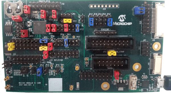
The MEC1501 Modular card ASSY6885 is a development board to evaluate the Microchip MEC152X series microcontrollers. This board can work standalone or be mated with any platform that complies with MECC specification.
Hardware
MEC1521HA0SZ ARM Cortex-M4 Processor
256 KB RAM and 64 KB boot ROM
GPIO headers
UART1 using microUSB
PECI interface 3.0
10 SMBUS instances
FAN, PMW and TACHO pins
VCI interface
Independent Hardware Driven PS/2 Ports
At difference from MEC15xx evaluation board, modular MEC1521 exposes the pins in 2 different ways:
Standalone mode via headers
GPIOs
PWM5
JTAG/SWD, ETM and MCHP Trace ports
eSPI bus
SMB0
Mated mode with another platform that has a high density MECC connector.
FAN0, PWM0, SMB0, SMB1, SMB4 and SMB5
eSPI bus
Breathing/Blinking LEDs
The board is powered through the +5V USB Micro A connector or from the MECC connector.
For more information about the SOC please see the MEC152x Reference Manual [1]
Supported Features
The mec1501modular_assy6885 board configuration supports the following hardware features:
Interface |
Controller |
Driver/Component |
|---|---|---|
NVIC |
on-chip |
nested vector interrupt controller |
SYSTICK |
on-chip |
systick |
UART |
on-chip |
serial port |
GPIO |
on-chip |
gpio |
ESPI |
on-chip |
espi |
I2C |
on-chip |
i2c |
PINMUX |
on-chip |
pinmux |
RTOS |
on-chip |
timer |
TIMER |
on-chip |
counter |
PWM |
on-chip |
pwm |
ADC |
on-chip |
adc |
WATCHDOG |
on-chip |
watchdog |
PS2 |
on-chip |
ps2 |
Other hardware features are not currently supported by Zephyr (at the moment)
The default configuration can be found in the boards/arm/mec1501modular_assy6885/mec1501modular_assy6885_defconfig Kconfig file.
Connections and IOs
This evaluation board kit is comprised of the following HW blocks:
MEC1501 Modular Card ASSY 6885 Rev A0 MEC1501 Modular EC Card - Assy_6885 Rev A0p1 [2]
System Clock
The MEC1501 MCU is configured to use the 48Mhz internal oscillator with the on-chip PLL to generate a resulting EC clock rate of 12 MHz. See Processor clock control register in chapter 4 “4.0 POWER, CLOCKS, and RESETS” of the data sheet in the references at the end of this document.
Serial Port
UART1 is configured for serial logs.
Jumper settings
Please follow the jumper settings below to properly demo this board. Advanced users may deviate from this recommendation.
Jumper setting for MEC1501 Modular Assy 6885 Rev A1p0
Boot-ROM Straps
These jumpers configure MEC1501 Boot-ROM straps.
JP37 (CMP_STRAP) |
J6 (CR_STRAP) |
JP41 (VTR2_STRAP) |
JP23 (BSS_STRAP) |
|---|---|---|---|
1-2 |
1-2 |
1-2 |
3-4 |
JP23 3-4 pulls SHD SPI CS0# up to VTR2. MEC1501 Boot-ROM samples
SHD SPI CS0# and if high, it loads code from SHD SPI.
This is the recommended setup.
CR_STRAP |
BSS_STRAP |
SOURCE |
0 |
X |
Use 3.3V Private SPI |
1 |
0 |
Use eSPI Flash channel |
1 |
Use 3.3V Shared channel(R) |
Power management
JP20 2-3 is required so all GPIOs powered by VTR3 rail worked at 1.8V.
Note
External 1.8V needs to be connected to JP13.1
JP20 (VTR3 selection) |
JP13 (1.8V source) |
|---|---|
2-3 |
1.8V to pin 1 |
Jumper location map
+--------------------------------------------------------------------------------------+
|                  |------------|                     +----------+ J10              || |
|  [BT1]       +   +------------+ J50                                      ++   ++  || |
|              |                                           JP38 JP43       ++   ||  || |
|              +         +      +       +-+ JP4              +    +       JP26  ||  || |
|             JP6        +      +                  +      +  + +  + +           ||  || |
|    JP31 ++            JP32   JP36     +-+ JP27   +      +    +    +           J6  || |
|                                                 JP18  JP37 JP41 JP42              ++ |
|         ++                  +   +    +--------+                                  J48 |
|         ||  JP21            +   +    +--------+ JP22    +----------+                 |
|      J2 ||   +            JP34 JP30                         J11              ++      |
|         ++   +                                                  J44          ||      |
|                            ++                         +----------------+     ||      |
|       +---------------+    ||  +        JP24          |----------------|     ++      |
|       |---------------|    ++  +    +----------+      +----------------+    J47      |
| JP20  +---------------+  JP23  JP40 +----------+                                  ++ |
|                                                     +           ++ JP29           || |
|                             +  +    +----------+    +                             || |
|    J52+---------------+     +  +    +----------+   J5   +-------------+           ++ |
|    J45+---------------+  JP33 TP57      JP25            +-------------+ J4       J49 |
|                                                                                      |
| ++                                           TP4   +----------+   ++                 |
| ++     +    +      +    +    +       +  TP61         +----------+   ++               |
| JP28   +    +      +    +    +  TP65 +  TP60            J51        JP35              |
|      TP58 JP16   JP11 JP13 JP15     JP10                                             |
| TP5                                                                                  |
| TP6                                        TP1                                       |
+--------------------------------------------------------------------------------------+
Programming and Debugging
Setup
Clone the MEC152x SPI Image Gen [3] repository or download the files within that directory. For the pre-production MEC150x use the MEC150x SPI Image Gen [4] repository.
Make the image generation available for Zephyr, by making the tool searchable by path, or by setting an environment variable
EVERGLADES_SPI_GEN, for example:export EVERGLADES_SPI_GEN=<path to tool>/everglades_spi_gen_RomENote that the tools for Linux and Windows have different file names. For the pre-production MEC1501 SOC use everglades_spi_gen_lin64.
If needed, a custom SPI image configuration file can be specified to override the default one.
export EVERGLADES_SPI_CFG=custom_spi_cfg.txt
Building
Build Hello World application as you would normally do.
Once you have
zephyr.bin, use the MEC152x SPI Image Gen [3] microchip tool to create the final binary. You need the output from this tool to flash in the SHD SPI memory.
Flashing
Connect Dediprog into header
J2.Flash the SPI NOR
U3at offset 0x0 using Dediprog SF100 or a similar tool for flashing SPI chips.Run your favorite terminal program to listen for output. Under Linux the terminal should be
/dev/ttyACM0. For example:$ minicom -D /dev/ttyACM0 -o
The -o option tells minicom not to send the modem initialization string. Connection should be configured as follows:
Speed: 115200
Data: 8 bits
Parity: None
Stop bits: 1
Connect the MEC1501MODULAR_ASSY6885 board to your host computer using the UART1 port and apply power.
You should see
"Hello World! mec1501modular_assy6885"in your terminal.
Debugging
This board comes with a Cortex ETM port which facilitates tracing and debugging using a single physical connection. In addition, it comes with sockets for JTAG only sessions.
HW Issues
In case you don’t see your application running, please make sure LED1 is lit.
If is off, then check the power related jumpers again.