OLIMEX-STM32-P405
Overview
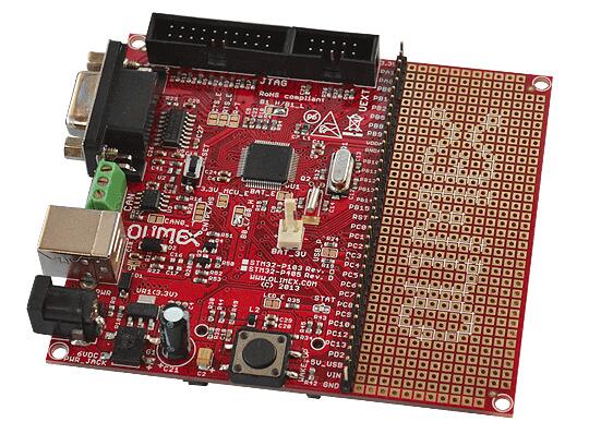
The OLIMEX-STM32-P405 board is based on the STMicroelectronics STM32F405RG ARM Cortex-M4 CPU.
OLIMEX-STM32-P405
Hardware
Information about the board can be found at the OLIMEX-STM32-P405 website and OLIMEX-STM32-P405 user manual. The ST STM32F405RG Datasheet contains the processor’s information and the datasheet.
Supported Features
The olimex_stm32_p405 board configuration supports the following hardware features:
Interface |
Controller |
Driver/Component |
|---|---|---|
NVIC |
on-chip |
nested vectored interrupt controller |
SYSTICK |
on-chip |
system clock |
UART |
on-chip |
serial port |
GPIO |
on-chip |
gpio |
Other hardware features have not been enabled yet for this board.
Pin Mapping
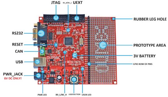
OLIMEX-STM32-P405 connectors
LED
USER_LED (red) = PC12
PWR_LED (red) = power
External Connectors
JTAG debug
PIN # |
Signal Name |
Pin # |
Signal Name |
|---|---|---|---|
1 |
+3.3V |
11 |
|
2 |
+3.3V |
12 |
GND |
3 |
PB4 / TRST |
13 |
PB3 / TDO |
4 |
GND |
14 |
GND |
5 |
PA15 / TDI |
15 |
PB4 / TRST |
6 |
GND |
16 |
GND |
7 |
PA13 / TMS |
17 |
|
8 |
GND |
18 |
GND |
9 |
PA14 / TCK |
19 |
+5V_JTAG |
10 |
GND |
20 |
GND |
UEXT
PIN # |
Wire Name |
STM32F405 port |
|---|---|---|
1 |
+3.3V |
|
2 |
GND |
|
3 |
PA9/USART1_TX |
PA9 |
4 |
PA10/USART1_RX |
PA10 |
5 |
PB6/I2C1_SCL |
PB6 |
6 |
PB7/I2C1_SDA |
PB7 |
7 |
PA6/SPI1_MISO |
PA6 |
8 |
PA7/SPI1_MOSI |
PA7 |
9 |
PA5/SPI1_SCK |
PA5 |
10 |
PA4/SPI1_NSS |
PA4 |
GPIO row of pins
Pin |
STM32F405 Pin Functions |
|---|---|
3V3 |
N/A |
PA1 |
PA1/USART2_RTS/ADC1/TIM2_CH2 |
PA8 |
PA8/USART1_CK/TIM1_CH1/MCO |
PB0 |
PB0/ADC8/TIM3_CH3/TIM1_CH2N |
PB1 |
PB1/ADC9/TIM3_CH4/TIM1_CH3N |
PB2 |
PB2/BOOT1 |
PB5 |
PB5/I2C1_SMBAI/TIM3_CH2/SPI1_MOSI |
PB8 |
PB8/TIM4_CH3/I2C1_SCL/CANRX |
PB9 |
PB9/TIM4_CH4/I2C1_SDA/CANTX |
VDDA |
N/A |
GNDA |
N/A |
PB10 |
PB10/I2C2_SCL/USART3_TX/TIM2_CH3 |
PB11 |
PB11/I2C2_SDA/USART3_RX/TIM2_CH4 |
PB12 |
PB12/SPI2_NSS/I2C2_SMBAL/USART3_CK/TIM1_BKIN |
PB13 |
PB13/SPI2_SCK/USART3_CTS/TIM1_CH1N |
PB14 |
PB14/SPI2_MISO/USART3_RTS/TIM1_CH2N |
PB15 |
PB15/SPI2_MOSI/TIM1_CH3N |
RST |
NRST |
PC0 |
PC0/ADC10 |
PC1 |
PC1/ADC11 |
PC2 |
PC2/ADC12 |
PC3 |
PC3/ADC13 |
PC4 |
PC4/ADC14 |
PC5 |
PC5/ADC15 |
PC6 |
PC6/TIM3_CH1 |
PC7 |
PC7/TIM3_CH2 |
PC8 |
PC8/TIM3_CH3 |
PC9 |
PC9/TIM3_CH4 |
PC10 |
PC10/USART3_TX |
PC12 |
PC12/USART3_CK |
PC13 |
PC13/ANTI_TAMP |
PD2 |
PD2/TIM3_ETR |
+5V_USB |
N/A |
VIN |
N/A |
GND |
N/A |
System Clock
OLIMEX-STM32-P405 has two external oscillators. The frequency of the slow clock is 32.768 kHz. The frequency of the main clock is 8 MHz. The processor can setup HSE to drive the master clock, which can be set as high as 168 MHz.
Programming and Debugging
The OLIMEX-STM32-P405 board does not include an embedded debug tool interface. You will need to use ST tools or an external JTAG probe. In the following examples a ST-Link V2 USB dongle is used.
Flashing an application to the Olimex-STM32-P405
The sample application Hello World is being used in this tutorial.
Connect the ST-Link USB dongle to your host computer and to the JTAG port of the OLIMEX-STM32-P405 board.
Now build and flash the application.
# From the root of the zephyr repository
west build -b olimex_stm32_p405 samples/hello_world
west flash
Run a serial host program to connect with your board:
$ minicom -D /dev/ttyACM0
After resetting the board, you should see the following message:
***** BOOTING ZEPHYR OS v1.8.99 - BUILD: Aug  4 2017 14:54:40 *****
Hello World! arm
Debugging
You can debug an application in the usual way. Here is an example for the Hello World application.
# From the root of the zephyr repository
west build -b olimex_stm32_p405 samples/hello_world
west debug