Thingy:52
Overview
Zephyr uses the thingy52_nrf52832 (PCA20020) board configuration for building for the Thingy:52 board. The board has the nRF52832 MCU with ARM Cortex-M4F processor, a set of environmental sensors, a pushbutton, and two RGB LEDs.
ADC
CLOCK
FLASH
Gas sensor
GPIO
GPIO Expander
Humidity and temperature sensor
I2C
MPU
NVIC
Pressure sensor
PWM
RADIO (Bluetooth Low Energy)
RGB LEDs
RTC
SPI
UART
WDT
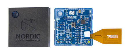
nRF52 Thingy:52 (Credit: Nordic Semiconductor)
More information about the board can be found at the nRF52 DK website [1]. The Nordic Semiconductor Infocenter [2] contains the processor’s information and the datasheet.
Hardware
Thingy:52 has the following features:
Two RGB LEDs
CO2 and TVOC sensor
Humidity and temperature sensor
Color sensor
I2C GPIO expander
Provisions for a pin header and I2C and serial connectors
Bluetooth radio
Supported Features
Interface |
Controller |
Driver/Component |
|---|---|---|
ADC |
on-chip |
adc |
CLOCK |
on-chip |
clock_control |
FLASH |
on-chip |
flash |
Gas Sensor |
on-board |
ccs811 |
GPIO |
on-chip |
gpio |
GPIO Exp |
on-board |
sx1509b |
Humidity and Temp |
on-board |
hts221 |
I2C(M) |
on-chip |
i2c |
MPU |
on-chip |
arch/arm |
NVIC |
on-chip |
arch/arm |
Pressure and Temp |
on-board |
lps22hb_press |
PWM |
on-chip |
pwm |
RADIO |
on-chip |
Bluetooth |
RTC |
on-chip |
system clock |
SPI(M/S) |
on-chip |
spi |
UART |
on-chip |
serial |
WDT |
on-chip |
watchdog |
Connections and IOs
Lightwell RGB LED
The LED is driven by the SX1509B GPIO expander chip (device name GPIO_P0).
GPIO Expander Pin |
LED Channel |
|---|---|
5 |
Green |
6 |
Blue |
7 |
Red |
Serial
By default the system UART has the following pin configuration:
SOC Pin |
Signal |
|---|---|
P0.02 |
TX |
P0.03 |
RX |
The pins can be found on the P4 and P6 connectors. The system UART console uses these pins by default.
Internal I2C Bus
The internal I2C bus (I2C_0) is not routed to any of the external connectors, but most of the on-board devices are accessed through it. The following pins have been assigned to the bus:
SOC Pin |
Signal |
|---|---|
P0.07 |
SDA |
P0.08 |
SCL |
The following devices are attached to the bus.
Device |
Address |
|---|---|
SX1509B |
0x3e |
LPS22HB |
0x5c |
HTS221 |
0x5f |
CCS811 |
0x5a |
External I2C Bus
The external I2C bus (I2C_1) can be found on the P4 header and the P5 and P7 connectors.
SOC Pin |
Signal |
|---|---|
P0.14 |
SDA_EXT |
P0.15 |
SCL_EXT |
Pin Header
This is the pinout of the P4 pin header. Some of the SOC GPIO pins and I2C GPIO expander pins are accessible through it. It also allows attaching external devices to the four on-board N-channel MOSFET transistors.
Pin |
Device |
Signal / Device Pin |
|---|---|---|
1 |
SOC |
SCL_EXT / P0.15 |
2 |
SOC |
SDA_EXT / P0.14 |
3 |
SOC |
ANA/DIG0 / P0.02 |
4 |
SOC |
ANA/DIG1 / P0.03 |
5 |
SOC |
ANA/DIG2 / P0.04 |
6 |
GND |
|
7 |
GPIO Expander |
Pin 0 |
8 |
GPIO Expander |
Pin 1 |
9 |
GPIO Expander |
Pin 2 |
10 |
GPIO Expander |
Pin 3 |
11 |
MOSFET 1 |
Drain |
12 |
MOSFET 1 |
Source |
13 |
MOSFET 2 |
Drain |
14 |
MOSFET 2 |
Source |
15 |
MOSFET 3 |
Drain |
16 |
MOSFET 3 |
Source |
17 |
MOSFET 4 |
Drain |
18 |
MOSFET 4 |
Source |
19 |
VDD |
|
20 |
GND |
MOSFETs
The MOSFETs are attached to the following SOC GPIO pins:
Device |
Gate Pin |
|---|---|
MOSFET 1 |
P0.18 |
MOSFET 2 |
P0.19 |
MOSFET 3 |
P0.20 |
MOSFET 4 |
P0.21 |
Power Rails
Thing:52 has multiple power rails. The necessary rails for the currently supported devices are listed here.
Name |
Derived from |
Controlled by |
|---|---|---|
VREG |
The battery |
Always on |
VDD_nRF |
VREG |
Always on |
VDD |
VREG |
SOC pin P0.30 |
VDD_CCS |
VDD |
GPIO expander pin 10 |
Due to the dependencies of the power rails, multiple rails may need to be powered for a given device to turn on. The correct order of powering up the rails is the order of the rails down the dependency chain. For example, in order to power the CCS811 gas sensor, VDD has to be turned on first and VDD_CCS after it. Here’s a list of the devices and their power rails:
Device |
Rail |
|---|---|
nRF52832 |
VDD_nRF |
SX1509B |
VDD |
LPS22HB |
VDD |
HTS221 |
VDD |
CCS811 |
VDD_CCS |
Sensors
Device |
Function |
Bus |
I2C Address |
Power Rail |
|---|---|---|---|---|
LPS22HB |
Pressure and Temperature sensor |
I2C_0 |
0x5c |
VDD |
HTS221 |
Humidity and Temperature sensor |
I2C_0 |
0x5f |
VDD |
CCS811 |
Gas sensor |
I2C_0 |
0x5a |
VDD_CCS |
Misc. Device Pins
SX1509B
Device Signal |
SOC Pin |
|---|---|
SX_OSCIO |
P0.05 |
SX_RESET |
P0.16 |
LPS22HB
Sensor Signal |
SOC Pin |
|---|---|
LPS_INT |
P0.23 |
HTS221
Sensor Signal |
SOC Pin |
|---|---|
HTS_INT |
P0.24 |
CCS811
Sensor Signal |
GPIO Expander Pin |
|---|---|
CCS_RESET |
11 |
CCS_WAKE |
12 |
Programming and Debugging
Flashing
Flashing Zephyr onto Thingy:52 requires an external J-Link programmer. The programmer is attached to the P9 programming header.
Debugging
Thingy:52 does not have an on-board J-Link debug IC as some other nRF5 development boards, however, instructions from the Nordic nRF5x Segger J-Link page also apply to this board, with the additional step of connecting an external debugger. A development board with a Debug out connector such as the nRF52 DK can be used as a debugger with Thingy:52.
Testing board features
The green lightwell LED can be tested with the Blinky example.
# From the root of the zephyr repository
west build -b thingy52_nrf52832 samples/basic/blinky
west flash
Also the temperature and humidity sensor can be tested with the HTS221: Temperature and Humidity Monitor sample.
# From the root of the zephyr repository
west build -b thingy52_nrf52832 samples/sensor/hts221
west flash