Raspberry Pi Pico
Overview
The Raspberry Pi Pico and Pico W are small, low-cost, versatile boards from Raspberry Pi. They are equipped with an RP2040 SoC, an on-board LED, a USB connector, and an SWD interface. The Pico W additionally contains an Infineon CYW43439 2.4 GHz Wi-Fi/Bluetoth module. The USB bootloader allows the ability to flash without any adapter, in a drag-and-drop manner. It is also possible to flash and debug the boards with their SWD interface, using an external adapter.
Hardware
Dual core Arm Cortex-M0+ processor running up to 133MHz
264KB on-chip SRAM
2MB on-board QSPI flash with XIP capabilities
26 GPIO pins
3 Analog inputs
2 UART peripherals
2 SPI controllers
2 I2C controllers
16 PWM channels
USB 1.1 controller (host/device)
8 Programmable I/O (PIO) for custom peripherals
On-board LED
1 Watchdog timer peripheral
Infineon CYW43439 2.4 GHz Wi-Fi chip (Pico W only)
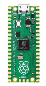
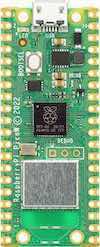
Raspberry Pi Pico (above) and Pico W (below) (Images courtesy of Raspberry Pi)
Supported Features
The rpi_pico board configuration supports the following hardware features:
Peripheral |
Kconfig option |
Devicetree compatible |
|---|---|---|
NVIC |
N/A |
|
UART |
||
GPIO |
||
ADC |
||
I2C |
||
SPI |
||
USB Device |
||
HWINFO |
N/A |
|
Watchdog Timer (WDT) |
||
PWM |
||
Flash |
|
|
Clock controller |
||
UART (PIO) |
||
SPI (PIO) |
Pin Mapping
The peripherals of the RP2040 SoC can be routed to various pins on the board. The configuration of these routes can be modified through DTS. Please refer to the datasheet to see the possible routings for each peripheral.
External pin mapping on the Pico W is identical to the Pico, but note that internal RP2040 GPIO lines 23, 24, 25, and 29 are routed to the Infineon module on the W. Since GPIO 25 is routed to the on-board LED on the Pico, but to the Infineon module on the Pico W, the “blinky” sample program does not work on the W (use hello_world for a simple test program instead).
Default Zephyr Peripheral Mapping:
UART0_TX : P0
UART0_RX : P1
I2C0_SDA : P4
I2C0_SCL : P5
I2C1_SDA : P14
I2C1_SCL : P15
SPI0_RX : P16
SPI0_CSN : P17
SPI0_SCK : P18
SPI0_TX : P19
ADC_CH0 : P26
ADC_CH1 : P27
ADC_CH2 : P28
ADC_CH3 : P29
Programmable I/O (PIO)
The RP2040 SoC comes with two PIO periherals. These are two simple co-processors that are designed for I/O operations. The PIOs run a custom instruction set, generated from a custom assembly language. PIO programs are assembled using pioasm, a tool provided by Raspberry Pi.
Zephyr does not (currently) assemble PIO programs. Rather, they should be manually assembled and embedded in source code. An example of how this is done can be found at drivers/serial/uart_rpi_pico_pio.c.
Sample: SPI via PIO
The samples/sensor/bme280/README.rst sample includes a demonstration of using the PIO SPI driver to communicate with an environmental sensor. The PIO SPI driver supports using any combination of GPIO pins for an SPI bus, as well as allowing up to four independent SPI buses on a single board (using the two SPI devices as well as both PIO devices).
Programming and Debugging
Flashing
Using SEGGER JLink
You can Flash the rpi_pico with a SEGGER JLink debug probe as described in Building, Flashing and Debugging.
Here is an example of building and flashing the Blinky application.
# From the root of the zephyr repository
west build -b rpi_pico samples/basic/blinky
west flash --runner jlink
Using OpenOCD
To use PicoProbe, You must configure udev.
Create a file in /etc/udev.rules.d with any name, and write the line below.
ATTRS{idVendor}=="2e8a", ATTRS{idProduct}=="000c", MODE="660", GROUP="plugdev", TAG+="uaccess"
This example is valid for the case that the user joins to plugdev groups.
The Raspberry Pi Pico has an SWD interface that can be used to program and debug the on board RP2040. This interface can be utilized by OpenOCD. To use it with the RP2040, OpenOCD version 0.12.0 or later is needed.
If you are using a Debian based system (including RaspberryPi OS, Ubuntu. and more), using the pico_setup.sh [1] script is a convenient way to set up the forked version of OpenOCD.
Depending on the interface used (such as JLink), you might need to checkout to a branch that supports this interface, before proceeding. Build and install OpenOCD as described in the README.
Here is an example of building and flashing the Blinky application.
# From the root of the zephyr repository
west build -b rpi_pico samples/basic/blinky -- -DOPENOCD=/usr/local/bin/openocd -DOPENOCD_DEFAULT_PATH=/usr/local/share/openocd/scripts -DRPI_PICO_DEBUG_ADAPTER=picoprobe
west flash
Set the environment variables OPENOCD to /usr/local/bin/openocd and OPENOCD_DEFAULT_PATH to /usr/local/share/openocd/scripts. This should work with the OpenOCD that was installed with the default configuration. This configuration also works with an environment that is set up by the pico_setup.sh [1] script.
RPI_PICO_DEBUG_ADAPTER specifies what debug adapter is used for debugging.
If RPI_PICO_DEBUG_ADAPTER was not assigned, picoprobe is used by default. The other supported adapters are raspberrypi-swd, jlink and blackmagicprobe. How to connect picoprobe and raspberrypi-swd is described in Getting Started with Raspberry Pi Pico [2]. Any other SWD debug adapter maybe also work with this configuration.
The value of RPI_PICO_DEBUG_ADAPTER is cached, so it can be omitted from west flash and west debug if it was previously set while running west build.
RPI_PICO_DEBUG_ADAPTER is used in an argument to OpenOCD as “source [find interface/${RPI_PICO_DEBUG_ADAPTER}.cfg]”. Thus, RPI_PICO_DEBUG_ADAPTER needs to be assigned the file name of the debug adapter.
You can also flash the board with the following command that directly calls OpenOCD (assuming a SEGGER JLink adapter is used):
$ openocd -f interface/jlink.cfg -c 'transport select swd' -f target/rp2040.cfg -c "adapter speed 2000" -c 'targets rp2040.core0' -c 'program path/to/zephyr.elf verify reset exit'
Using UF2
If you don’t have an SWD adapter, you can flash the Raspberry Pi Pico with a UF2 file. By default, building an app for this board will generate a build/zephyr/zephyr.uf2 file. If the Pico is powered on with the BOOTSEL button pressed, it will appear on the host as a mass storage device. The UF2 file should be drag-and-dropped to the device, which will flash the Pico.
Debugging
The SWD interface can also be used to debug the board. To achieve this, you can either use SEGGER JLink or OpenOCD.
Using SEGGER JLink
Use a SEGGER JLink debug probe and follow the instruction in Building, Flashing and Debugging.
Using OpenOCD
Install OpenOCD as described for flashing the board.
Here is an example for debugging the Blinky application.
# From the root of the zephyr repository
west build -b rpi_pico samples/basic/blinky -- -DOPENOCD=/usr/local/bin/openocd -DOPENOCD_DEFAULT_PATH=/usr/local/share/openocd/scripts -DRPI_PICO_DEBUG_ADAPTER=raspberrypi-swd
west debug
As with flashing, you can specify the debug adapter by specifying RPI_PICO_DEBUG_ADAPTER at west build time. No needs to specify it at west debug time.
You can also debug with OpenOCD and gdb launching from command-line. Run the following command:
$ openocd -f interface/jlink.cfg -c 'transport select swd' -f target/rp2040.cfg -c "adapter speed 2000" -c 'targets rp2040.core0'
On another terminal, run:
$ gdb-multiarch
Inside gdb, run:
(gdb) tar ext :3333
(gdb) file path/to/zephyr.elf
You can then start debugging the board.