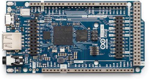
Arduino GIGA R1 WiFi
Overview
Arduino GIGA R1 WiFi is a development board by Arduino based on the STM32H747XI, a dual core ARM Cortex-M7 + Cortex-M4 MCU, with 2MBytes of Flash memory and 1MB SRAM.
The board features:
RGB LED
Reset and Boot buttons
USB-C device
USB Host
16MB external QSPI flash
8MB external SDRAM
Murata Type 1DX Bluetooth + WiFi module (CYW4343W based)
Audio jack
ATECC608A secure element
More information about the board, including the datasheet, pinout and schematics, can be found at the Arduino GIGA website.
More information about STM32H747XIH6 can be found here:
Supported Features
The current Zephyr arduino_giga_r1_m7 board configuration supports the
following hardware features:
Interface |
Controller |
Driver/Component |
|---|---|---|
NVIC |
on-chip |
nested vector interrupt controller |
UART |
on-chip |
serial port-polling; serial port-interrupt |
PINMUX |
on-chip |
pinmux |
GPIO |
on-chip |
gpio |
FLASH |
on-chip |
flash memory |
RNG |
on-chip |
True Random number generator |
I2C |
on-chip |
i2c |
SPI |
on-chip |
spi |
IPM |
on-chip |
virtual mailbox based on HSEM |
FMC |
on-chip |
memc (SDRAM) |
QSPI |
on-chip |
QSPI flash |
RADIO |
Murata 1DX |
WiFi and Bluetooth module |
Other hardware features are not yet supported on Zephyr port.
Fetch Binary Blobs
The board Bluetooth/WiFi module requires fetching some binary blob files, to do that run the command:
west blobs fetch hal_infineon
Note
Only Bluetooth functionality is currently supported.
Resources sharing
The dual core nature of STM32H747 SoC requires sharing HW resources between the two cores. This is done in 3 ways:
Compilation: Clock configuration is only accessible to M7 core. M4 core only has access to bus clock activation and deactivation.
Static pre-compilation assignment: Peripherals such as a UART are assigned in devicetree before compilation. The user must ensure peripherals are not assigned to both cores at the same time.
Run time protection: Interrupt-controller and GPIO configurations could be accessed by both cores at run time. Accesses are protected by a hardware semaphore to avoid potential concurrent access issues.
Programming and Debugging
Applications for the arduino_giga_r1 board should be built per core target,
using either arduino_giga_r1_m7 or arduino_giga_r1_m4 as the target.
See Building an Application for more information about application builds.
Flashing
This board can be flashed either using dfu-util, or with an external debugging probe, such as a J-Link or Black Magic Probe, connected to the on board MIPI-10 SWD port marked as “JTAG”.
Note
The board ships with a custom Arduino bootloader programmed in the first
flash page that can be triggered by double clicking the RST button. This
bootloader is USB-DFU compatible and supports programming both the internal
and external flash and is the one used by west flash by default. The
internal STM32 ROM bootloader can also be used by pressing RST while
holding the BOOT0 button, this also supports USB-DFU but can only
program the internal flash and can overwrite the Arduino bootloader. More
details can be found in the “Boot0” section of the Arduino GIGA Cheat
Sheet.
First, connect the Arduino GIGA R1 board to your host computer using the USB
port to prepare it for flashing. Double click the RST button to put the
board into the Arduino Bootloader mode. Then build and flash your application.
Here is an example for the Hello World application.
# From the root of the zephyr repository
west build -b arduino_giga_r1_m7 samples/hello_world
west flash
Run a serial host program to connect with your board:
$ minicom -D /dev/ttyACM0
You should see the following message on the console:
Hello World! arduino_giga_r1_m7
Similarly, you can build and flash samples on the M4 target.
Here is an example for the Blinky application on M4 core.
# From the root of the zephyr repository
west build -b arduino_giga_r1_m4 samples/basic/blinky
west flash
Debugging
Debugging is supported by using west debug with an external probe such as a
J-Link or Black Magic Probe, connected to the on board MIPI-10 SWD port marked
as “JTAG”. For example:
west debug -r jlink