ST STM32MP157C-DK2 Discovery
Overview
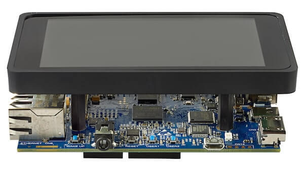
The STM32MP157-DK2 Discovery board leverages the capacities of the STM32MP157 multi-core processor,composed of a dual Cortex®-A7 and a single Cortex®-M4 core. Zephyr OS is ported to run on the Cortex®-M4 core.
Common features:
STM32MP157:
Arm®-based dual Cortex®-A7 32 bits
Cortex®-M4 32 bits
embedded SRAM (448 Kbytes) for Cortex®-M4.
ST PMIC STPMIC1A
4-Gbit DDR3L, 16 bits, 533 MHz
1-Gbps Ethernet (RGMII) compliant with IEEE-802.3ab
USB OTG HS
Audio CODEC, with a stereo headset jack, including analog microphone input
4 user LEDs
2 user and reset push-buttons, 1 wake-up button
5 V / 3 A USB Type-CTM power supply input (not provided)
Board connectors:
Ethernet RJ45
4 USB Host Type-A
USB Type-C
DRP MIPI DSI HDMI
Stereo headset jack including analog microphone input
microSD card
GPIO expansion connector (Raspberry Pi® shields capability)
ArduinoTM Uno V3 expansion connectors
On-board ST-LINK/V2-1 debugger/programmer with USB re-enumeration capability: Virtual COM port and debug port
Board-specific features:
4” TFT 480×800 pixels with LED backlight, MIPI DSI interface, and capacitive touch panel
Wi-Fi® 802.11b/g/n
Bluetooth® Low Energy 4.1
More information about the board can be found at the STM32P157C Discovery website.
Hardware
The STM32MP157 SoC provides the following hardware capabilities:
Core:
32-bit dual-core Arm® Cortex®-A7
L1 32-Kbyte I / 32-Kbyte D for each core
256-Kbyte unified level 2 cache
Arm® NEON™ and Arm® TrustZone®
32-bit Arm® Cortex®-M4 with FPU/MPU
Up to 209 MHz (Up to 703 CoreMark®)
Memories:
External DDR memory up to 1 Gbyte.
708 Kbytes of internal SRAM: 256 KB of AXI SYSRAM + 384 KB of AHB SRAM + 64 KB of AHB SRAM in backup domain.
Dual mode Quad-SPI memory interface
Flexible external memory controller with up to 16-bit data bus
Security/safety:
Secure boot, TrustZone® peripherals with Cortex®-M4 resources isolation
Clock management:
Internal oscillators: 64 MHz HSI oscillator, 4 MHz CSI oscillator, 32 kHz LSI oscillator
External oscillators: 8-48 MHz HSE oscillator, 32.768 kHz LSE oscillator
6 × PLLs with fractional mode
General-purpose input/outputs:
Up to 176 I/O ports with interrupt capability
Interconnect matrix
3 DMA controllers
Communication peripherals:
6 × I2C FM+ (1 Mbit/s, SMBus/PMBus)
4 × UART + 4 × USART (12.5 Mbit/s, ISO7816 interface, LIN, IrDA, SPI slave)
6 × SPI (50 Mbit/s, including 3 with full duplex I2S audio class accuracy)
4 × SAI (stereo audio: I2S, PDM, SPDIF Tx)
SPDIF Rx with 4 inputs
HDMI-CEC interface
MDIO Slave interface
3 × SDMMC up to 8-bit (SD / e•MMC™ / SDIO)
2 × CAN controllers supporting CAN FD protocol, TTCAN capability
2 × USB 2.0 high-speed Host+ 1 × USB 2.0 full-speed OTG simultaneously
10/100M or Gigabit Ethernet GMAC (IEEE 1588v2 hardware, MII/RMII/GMII/RGMI)
8- to 14-bit camera interface up to 140 Mbyte/s
6 analog peripherals
2 × ADCs with 16-bit max. resolution.
1 × temperature sensor
2 × 12-bit D/A converters (1 MHz)
1 × digital filters for sigma delta modulator (DFSDM) with 8 channels/6 filters
Internal or external ADC/DAC reference VREF+
Graphics:
3D GPU: Vivante® - OpenGL® ES 2.0
LCD-TFT controller, up to 24-bit // RGB888, up to WXGA (1366 × 768) @60 fps
MIPI® DSI 2 data lanes up to 1 GHz each
Timers:
2 × 32-bit timers with up to 4 IC/OC/PWM or pulse counter and quadrature (incremental) encoder input
2 × 16-bit advanced motor control timers
10 × 16-bit general-purpose timers (including 2 basic timers without PWM)
5 × 16-bit low-power timers
RTC with sub-second accuracy and hardware calendar
2 × 4 Cortex®-A7 system timers (secure, non-secure, virtual, hypervisor)
1 × SysTick Cortex®-M4 timer
Hardware acceleration:
AES 128, 192, 256, TDES
HASH (MD5, SHA-1, SHA224, SHA256), HMAC
2 × true random number generator (3 oscillators each)
2 × CRC calculation unit
Debug mode:
Arm® CoreSight™ trace and debug: SWD and JTAG interfaces
8-Kbyte embedded trace buffer
3072-bit fuses including 96-bit unique ID, up to 1184-bit available for user
More information about STM32P157C can be found here:
Supported Features
The Zephyr stm32mp157c_dk2 board configuration supports the following hardware features:
Interface |
Controller |
Driver/Component |
|---|---|---|
NVIC |
on-chip |
nested vector interrupt controller |
GPIO |
on-chip |
gpio |
UART |
on-chip |
serial port-polling; serial port-interrupt |
PINMUX |
on-chip |
pinmux |
I2C |
on-chip |
i2c |
SPI |
on-chip |
spi |
The default configuration can be found in the defconfig file:
boards/arm/stm32mp157c_dk2/stm32mp157c_dk2_defconfig
Connections and IOs
STM32MP157C-DK2 Discovery Board schematic is available here: STM32MP157C Discovery board schematics.
Default Zephyr Peripheral Mapping:
USART_3 TX/RX : PB10/PB12 (UART console)
UART_7 TX/RX : PE8/PE7 (Arduino Serial)
I2C5 SCL/SDA : PA11/PA12 (Arduino I2C)
SPI4 SCK/MISO/MOSI : PE12/PE13/PE14 (Arduino SPI)
SPI5 SCK/MISO/MOSI : PF7/PF8/PF9
System Clock
The Cortex®-M4 Core is configured to run at a 209 MHz clock speed. This value must match the configured mlhclk_ck frequency.
Serial Port
The STM32MP157C-DK2 Discovery board has 8 U(S)ARTs. The Zephyr console output is assigned by default to the RAM console to be dumped by the Linux Remoteproc Framework on Cortex®-A7 core. In order to keep the UART7 free for future serial interactions with Arduino shield, the Zephyr UART console output is USART3 and is disabled by default. UART console can be enable through board’s devicetree and stm32mp157c_dk2_defconfig board file (or prj.conf project files), and will disable existing RAM console output. Default UART console settings are 115200 8N1.
Programming and Debugging
The STM32MP157C doesn’t have QSPI flash for the Cortex®-M4 and it needs to be started by the Cortex®-A7 core. The Cortex®-A7 core is responsible to load the Cortex®-M4 binary application into the RAM, and get the Cortex®-M4 out of reset. The Cortex®-A7 can perform these steps at bootloader level or after the Linux system has booted.
The Cortex®-M4 can use up to 2 different RAMs. The program pointer starts at address 0x00000000 (RETRAM), the vector table should be loaded at this address These are the memory mappings for Cortex®-A7 and Cortex®-M4:
Region |
Cortex®-A7 |
Cortex®-M4 |
Size |
|---|---|---|---|
RETRAM |
0x38000000-0x3800FFFF |
0x00000000-0x0000FFFF |
64KB |
MCUSRAM |
0x10000000-0x1005FFFF |
0x10000000-0x1005FFFF |
384KB |
DDR |
0xC0000000-0xFFFFFFFF |
up to 1 GB |
Refer to stm32mp157c boot Cortex-M4 firmware wiki page for instruction to load and start the Cortex-M4 firmware.
Debugging
You can debug an application using OpenOCD and GDB. The Solution proposed below is based on the attach to a preloaded firmware, available only for a Linux environment. The firmware must first be loaded by the Cortex®-A7. Developer then attaches the debugger to the running Zephyr using OpenOCD.
Principle is to attach to the firmware already loaded by the Linux.
Build the sample:
west build -b stm32mp157c_dk2 samples/hello_world
Copy the firmware on the target filesystem, load it and start it (stm32mp157c boot Cortex-M4 firmware).
Attach to the target:
west attach