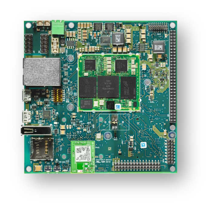
PhyBOARD Polis (NXP i.MX8M Mini)
Overview
The phyBOARD-Polis, either a development platform for the phyCORE-i.MX 8M Mini/Nano, or a powerful, industry-compatible single-board computer for immediate implementation of your product idea. As a development platform, the phyBOARD-Polis serves as reference design for your customer-specific application and enables parallel development of the software and carrier board for the phyCORE-i.MX 8M Mini/Nano.
As a powerful, industrial single-board computer (SBC), the phyBOARD-Polis is equipped with a variety of standard interfaces which are available on standard or socket/pin header connectors, while interesting extensions of the phyCORE-i.MX 8M Mini/Nano features such as CAN FD, WLAN and an integrated TPM chip further extend the range of applications that can be developed with the phyCORE-i.MX 8M Mini/Nano.
Board features:
RAM: 512MB - 4GB (LPDDR4)
Storage:
4GB - 128GB eMMC
8MB - 128MB SPI NOR Flash
microSD Interfacce
4kB EEPROM
Wireless:
WiFi: 802.11 b/g/n (ac) 2,4 GHz / 5 GHz
BLE 4.2
USB:
1x USB2.0 OTG
1x USB2.0
Ethernet: 1x 10/100/1000BASE-T
Interfaces: - 1x RS232 / RS485 - 2x UART - 3x I²C - 2x SPI - Up to 4x PWM - 4x SAI - 1x MIPI CSI-2 - 1x MIPI DSI-2 - 2x MMC/SD/SDIO - 1x PCIe (mini PCIE)
LEDs:
1x Status LED (3 Color LED)
1x Debug UART LED
Debug
JTAG 20-pin connector
MicroUSB for UART debug, two COM ports for A53 and M4
More information about the board can be found at the PHYTEC website.
Supported Features
The Zephyr mimx8mm_phyboard_polis board configuration supports the following hardware features:
Interface |
Controller |
Driver/Component |
|---|---|---|
NVIC |
on-chip |
nested vector interrupt controller |
SYSTICK |
on-chip |
systick |
CLOCK |
on-chip |
clock_control |
PINMUX |
on-chip |
pinmux |
UART |
on-chip |
serial port-polling; serial port-interrupt |
GPIO |
on-chip |
GPIO output GPIO input |
The default configuration can be found in the defconfig file: boards/arm/mimx8mm_phyboard_polis/mimx8mm_phyboard_polis_defconfig.
It is recommended to disable peripherals used by the M4 core on the Linux host.
Other hardware features are not currently supported with Zephyr on the M4-Core.
Connections and IOs
The following components are tested and working correctly.
UART:
Zephyr is configured to use UART4 on the PhyBoard Polis by default to minimize problems with the A53-Core because UART4 is only accessible from the M4-Core.
Board Name |
SoM Name |
Usage |
|---|---|---|
RS232/485 |
UART1 |
RS232 / RS485 with flow-control |
To WiFi Module |
UART2 |
UART to WiFi/BLE Module |
Debug USB(A53) |
UART3 |
UART Debug Console via USB |
Debug USB(M4) |
UART4 |
UART Debug Console via USB |
Note
Please note, that the to UART2 connected Wifi/BLE Module isn’t working with Zephyr yet.
Warning
On Boards with the version number 1532.1 UART4 isn’t connected to the Debug USB. UART4 connects to pin 10(RX) and 12(TX) on the X8 pinheader.
LEDs:
Zephyr has the 3-color status LED configured. The led0 alias (the standard Zephyr led) is configured to be the blue led. The LED can also light up in red and green.
GPIO:
The pinmuxing for the GPIOs is the standard pinmuxing of the mimx8mm devicetree created by NXP. You can find it here:
dts/arm/nxp/nxp_imx8m_m4.dtsi.
The Pinout of the PhyBOARD Polis can be found here:
System Clock
The M4 Core is configured to run at a 400 MHz clock speed.
Programming and Debugging
The i.MX8MM does not have a separate flash for the M4-Core. Because of this the A53-Core has to load the program for the M4-Core to the right memory address, set the PC and start the processor. This can be done with U-Boot or Phytec’s Linux BSP via remoteproc.
Because remoteproc in Phytec’s BSP only writes to the TCM memory area, everything was tested in this memory area.
You can read more about remoteproc in Phytec’s BSP here: Remoteproc BSP
These are the memory mapping for A53 and M4:
Region |
Cortex-A53 |
Cortex-M4 (System Bus) |
Cortex-M4 (Code Bus) |
Size |
|---|---|---|---|---|
OCRAM |
0x00900000-0x0093FFFF |
0x20200000-0x2023FFFF |
0x00900000-0x0093FFFF |
256KB |
TCMU |
0x00800000-0x0081FFFF |
0x20000000-0x2001FFFF |
128KB |
|
TCML |
0x007E0000-0x007FFFFF |
0x1FFE0000-0x1FFFFFFF |
128KB |
|
OCRAM_S |
0x00180000-0x00187FFF |
0x20180000-0x20187FFF |
0x00180000-0x00187FFF |
32KB |
For more information about memory mapping see the i.MX 8M Applications Processor Reference Manual (section 2.1.2 and 2.1.3)
At compilation time you have to choose which RAM will be used. This
configuration is done in the file boards/arm/mimx8mm_evk/mimx8mm_evk.dts
with “zephyr,flash” (when CONFIG_XIP=y) and “zephyr,sram” properties.
The available configurations are:
If you don’t want to use the TCM memory area, you can either overwrite the boards devicetree in your program or edit the board devicetree located here:
boards/arm/mimx8mm_phyboard_polis/mimx8mm_phyboard_polis.dts
You also have to set XIP=n or edit the boards defconfig file, if you don’t want the TCM memory area to be used. You can find the defconf file here:
boards/arm/mimx8mm_phyboard_polis/mimx8mm_phyboard_polis_defconfig.
The following configurations are possible for the flash and sram chosen nodes to change the used memory area:
"zephyr,flash"
- &tcml_code
- &ocram_code
- &ocram_s_code

"zephyr,sram"
- &tcmu_sys
- &ocram_sys
- &ocram_s_sys
Starting the M4-Core via U-Boot
Load the compiled zephyr.bin to memory address 0x4800000. This should output something like this:
u-boot=> tftp 0x48000000 192.168.3.10:zyphr.bin
Using ethernet@30be0000 device
TFTP from server 192.168.3.10; our IP address is 192.168.3.11
Filename 'zepyhr.bin'.
Load address: 0x48000000
Loading: ##
         2 KiB/s
done
Bytes transferred = 27240 (6a68 hex)
Because it’s not possible to load directly to the TCM memory area you have to copy the binaries. The last argument given is the size of the file in bytes, you can copy it from the output of the last command.
u-boot=> cp.b 0x48000000 0x7e0000 27240
And finaly starting the M4-Core at the right memory address:
u-boot=> bootaux 0x7e0000
## Starting auxiliary core stack = 0x20003A58, pc = 0x1FFE1905...
Starting the M4-Core via remoteproc
Copy the zepyhr.elf to /lib/firmware on the target. Maybe a Zephyr sample
will be included in a future BSP release.
Note
In order to use remoteproc you have to add imx8mm-phycore-rpmsg.dtbo at
the end of the line in the /boot/bootenv.txt, then reboot the target.
Warning
Remoteproc only reads firmware files from the /lib/firmware directory!
If you try to load a binary from another location unexpected errors will
occur!
To load and start a firmware use this commands:
target$ echo /lib/firmware/zepyhr.elf > /sys/class/remoteproc/remoteproc0/firmware
target$ echo start > /sys/class/remoteproc/remoteproc0/state
[   90.700611] remoteproc remoteproc0: powering up imx-rproc
[   90.706114] remoteproc remoteproc0: Direct firmware load for /lib/firmware/zepyhr.elf failed w2
[   90.716571] remoteproc remoteproc0: Falling back to sysfs fallback for: /lib/firmware/zepyhr.elf
[   90.739280] remoteproc remoteproc0: Booting fw image /lib/firmware/zepyhr.elf, size 599356
[   90.804448] remoteproc remoteproc0: remote processor imx-rproc is now up
The M4-Core is now started up and running. You can see the output from Zephyr on UART4.
Debugging
The PhyBOARD Polis can be debugged using a JTAG Debugger.
The easiest way to do that is to use a SEGGER JLink Debugger and Phytec’s
PEB-EVAL-01 Shield, which can be directly connected to the JLink.
You can find the JLink Software package here: JLink Software
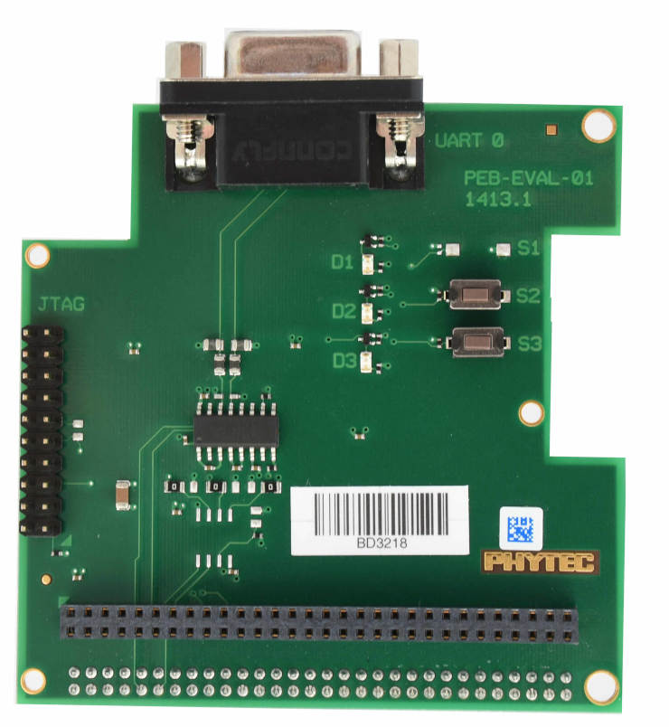
PEB-EVAL-01
To debug efficiently you should use multiple terminals:
(But its also possible to use west debug)
After connecting everything and building with west use this command while in the directory of the program you build earlier to start a debug server:
host$ west debugserver
West automatically connects via the JLink to the Target. And keeps open a debug server.
Use another terminal, start gdb, connect to target and load Zephyr on the target:
host$ gdb-multiarch build/zephyr/zephyr.elf -tui
(gdb) targ rem :2331
Remote debugging using :2331
0x1ffe0008 in _vector_table ()
(gdb) mon halt
(gdb) mon reset
(gdb) c
Continuing.
The program can be debugged using standard gdb techniques.