ST SensorTile.box
Overview
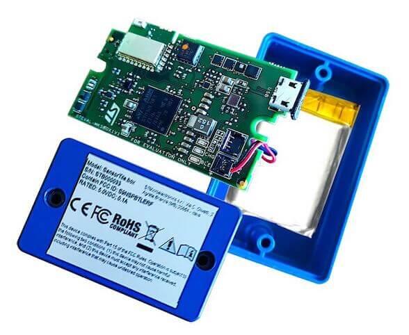
The STEVAL-MKSBOX1V1 (SensorTile.box) is a ready-to-use box kit for wireless IoT and wearable sensor platforms to help you use and develop apps based on remote motion and environmental sensor data. The SensorTile.box board fits into a small plastic box with a long-life rechargeable battery, and communicates with a standard smartphone through its Bluetooth interface, providing data coming from the sensors.
More information about the board can be found at the SensorTile.box website [1].
Hardware
SensorTile.box provides the following hardware components:
Ultra low-power STM32L4R9ZI System on Chip
LQFP144 package
Core: ARM® 32-bit Cortex®-M4 CPU with FPU, adaptive real-time accelerator (ART Accelerator) allowing 0-wait-state execution from Flash memory, frequency up to 120 MHz, MPU, 150 DMIPS/1.25 DMIPS/MHz (Dhrystone 2.1), and DSP instructions
Clock Sources:
16 MHz crystal oscillator
32 kHz crystal oscillator for RTC (LSE)
Communication
Bluetooth Smart connectivity v4.2 (SPBTLE-1S)
1 x USB OTG FS (SoC) with micro-B connector (USB device role only)
Internal Buses
3 x SPI bus
3 x I2C bus
micro-SD connector
On board sensors:
Digital temperature sensor (STTS751)
6-axis inertial measurement unit (LSM6DSOX)
3-axis accelerometers (LIS2DW12 and LIS3DHH)
3-axis magnetometer (LIS2MDL)
Altimeter / pressure sensor (LPS22HH)
Microphone / audio sensor (MP23ABS1)
Humidity sensor (HTS221)
HCP602535ZC LI-ion rechargeable battery (3.7V 500mAh)
FTSH107 connector for SWD debugging and UART Tx/Rx
Supported Features
The SensorTile.box provides motion, environmental, and audio sensor data through either the BLE or USB protocols to a host application running on a smartphone/PC to implement applications such as:
Pedometer optimized for belt positioning
Baby crying detection with Cloud AI learning
Barometer / environmental monitoring
Vehicle / goods tracking
Vibration monitoring
Compass and inclinometer
Sensor data logger
Connections and IOs
LED
Blue LED = PB15
Green LED = PF2
System Clock
SensorTile.box System Clock could be driven by internal or external oscillator, as well as main PLL clock. By default, the System clock is driven by the PLL clock at 80MHz, driven by the 16MHz external oscillator. The system clock can be boosted to 120MHz. The internal AHB/APB1/APB2 AMBA buses are all clocked at 80MHz.
Serial Port
There are two possible options for Zephyr console output:
using USART1 which is available on FTSH107 connector. In this case a JTAG adapter can be used to connect SensorTile.box to STLINK-V2 and have both SWD and console lines available on PC.
using the USB connector, which may be used to make the console available on PC as USB CDC class.
Console default settings are 115200 8N1.
USB interface
SensorTile.box can be connected as a USB device to a PC host through its micro-B connector. The final application may use it to declare SensorTile.box device as belonging to a certain standard or vendor class, e.g. a CDC, a mass storage or a composite device with both functions.
Programming and Debugging
There are 2 main entry points for flashing STM32FL4Rx SoCs, one using the ROM bootloader, and another by using the SWD debug port (which requires additional hardware) on FTSH107 connector. Flash using the ROM bootloader by powering on the board while keeping the BOOT0 button pressed. The ROM bootloader supports flashing via USB (DFU), UART, I2C and SPI. You can read more about how to enable and use the ROM bootloader by checking the application note AN2606 [2] (STM32L4Rx section).
Flashing
Installing dfu-util
It is recommended to use at least v0.8 of dfu-util. The package available in Debian and Ubuntu can be quite old, so you might have to build dfu-util from source. Information about how to get the source code and how to build it can be found at the DFU-UTIL website [3]
Flashing an Application to SensorTile.box
While pressing the BOOT0 button, connect the micro-USB cable to the USB OTG SensorTile.box port and to your computer. The board should be forced to enter DFU mode.
Confirm that the board is in DFU mode:
$ sudo dfu-util -l
dfu-util 0.9

Copyright 2005-2009 Weston Schmidt, Harald Welte and OpenMoko Inc.
Copyright 2010-2019 Tormod Volden and Stefan Schmidt
This program is Free Software and has ABSOLUTELY NO WARRANTY
Please report bugs to http://sourceforge.net/p/dfu-util/tickets/

Found DFU: [0483:df11] ver=2200, devnum=74, cfg=1, intf=0, path="2-2", alt=2, name="@OTP Memory /0x1FFF7000/01*0001Ke", serial="204A325D574D"
Found DFU: [0483:df11] ver=2200, devnum=74, cfg=1, intf=0, path="2-2", alt=1, name="@Option Bytes  /0x1FF00000/01*040 e/0x1FF01000/01*040 e", serial="204A325D574D"
Found DFU: [0483:df11] ver=2200, devnum=74, cfg=1, intf=0, path="2-2", alt=0, name="@Internal Flash  /0x08000000/512*0004Kg", serial="204A325D574D"
You should see following confirmation on your Linux host:
$ dmesg
usb 2-2: new full-speed USB device number 74 using xhci_hcd
usb 2-2: New USB device found, idVendor=0483, idProduct=df11
usb 2-2: New USB device strings: Mfr=1, Product=2, SerialNumber=3
usb 2-2: Product: STM32  BOOTLOADER
usb 2-2: Manufacturer: STMicroelectronics
usb 2-2: SerialNumber: 204A325D574D
You can build and flash the provided sample application (ST SensorTile.box) that reads sensors data and outputs values on the console.