ARM V2M Beetle
Overview
The v2m_beetle board configuration is used by Zephyr applications that run on the V2M Beetle board. It provides support for the Beetle ARM Cortex-M3 CPU and the following devices:
Nested Vectored Interrupt Controller (NVIC)
System Tick System Clock (SYSTICK)
Cortex-M System Design Kit GPIO
Cortex-M System Design Kit UART
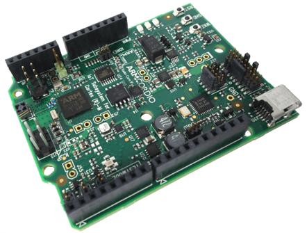
More information about the board can be found at the V2M Beetle Website.
Hardware
ARM V2M BEETLE provides the following hardware components:
ARM Cortex-M3
ARM IoT Subsystem for Cortex-M
CORDIO Bluetooth Smart radio
Memory
256KB of embedded flash
128KB SRAM
2MB of external QSPI flash.
Debug
JTAG, SWD & 4 bit TRACE
CMSIS-DAP with a virtual UART port
Arduino interface
GPIO, UART, SPI, I2C
Analog signals
Supported Features
The v2m_beetle board configuration supports the following hardware features:
Interface |
Controller |
Driver/Component |
|---|---|---|
NVIC |
on-chip |
nested vector interrupt controller |
SYSTICK |
on-chip |
systick |
UART |
on-chip |
serial port-polling; serial port-interrupt |
PINMUX |
on-chip |
pinmux |
GPIO |
on-chip |
gpio |
WATCHDOG |
on-chip |
watchdog |
TIMER |
on-chip |
timer |
Other hardware features are not currently supported by the port. See the V2M Beetle Website for a complete list of V2M Beetle board hardware features.
The default configuration can be found in the defconfig file:
boards/arm/v2m_beetle/v2m_beetle_defconfig
Interrupt Controller
Beetle is a Cortex-M3 based SoC and has 15 fixed exceptions and 45 IRQs.
A Cortex-M3/4-based board uses vectored exceptions. This means each exception calls a handler directly from the vector table.
Handlers are provided for exceptions 1-6, 11-12, and 14-15. The table here identifies the handlers used for each exception.
Exc# |
Name |
Remarks |
Used by Zephyr Kernel |
|---|---|---|---|
1 |
Reset |
system initialization |
|
2 |
NMI |
system fatal error |
|
3 |
Hard fault |
system fatal error |
|
4 |
MemManage |
MPU fault |
system fatal error |
5 |
Bus |
system fatal error |
|
6 |
Usage fault |
undefined instruction, or switch attempt to ARM mode |
system fatal error |
11 |
SVC |
system calls, kernel run-time exceptions, and IRQ offloading |
|
12 |
Debug monitor |
system fatal error |
|
14 |
PendSV |
context switch |
|
15 |
SYSTICK |
system clock |
Pin Mapping
The ARM V2M Beetle Board has 4 GPIO controllers. These controllers are responsible for pin muxing, input/output, pull-up, etc.
All GPIO controller pins are exposed via the following sequence of pin numbers:
Pins 0 - 15 are for GPIO 0
Pins 16 - 31 are for GPIO 1
Mapping from the ARM V2M Beetle Board pins to GPIO controllers:
D0 : P0_0
D1 : P0_1
D2 : P0_2
D3 : P0_3
D4 : P0_4
D5 : P0_5
D6 : P0_6
D7 : P0_7
D8 : P0_8
D9 : P0_9
D10 : P0_10
D11 : P0_11
D12 : P0_12
D13 : P0_13
D14 : P0_14
D15 : P0_15
D16 : P1_0
D17 : P1_1
D18 : P1_2
D19 : P1_3
D20 : P1_4
D21 : P1_5
D22 : P1_6
D23 : P1_7
D24 : P1_8
D25 : P1_9
D26 : P1_10
D27 : P1_11
D28 : P1_12
D29 : P1_13
D30 : P1_14
D31 : P1_15
Peripheral Mapping:
UART_0_RX : D0
UART_0_TX : D1
SPI_0_CS : D10
SPI_0_MOSI : D11
SPI_0_MISO : D12
SPI_0_SCLK : D13
I2C_0_SCL : D14
I2C_0_SDA : D15
UART_1_RX : D16
UART_1_TX : D17
SPI_1_CS : D18
SPI_1_MOSI : D19
SPI_1_MISO : D20
SPI_1_SCK : D21
I2C_1_SDA : D22
I2C_1_SCL : D23
For more details please refer to Beetle Technical Reference Manual (TRM).
System Clock
V2M Beetle has one external and two on-chip oscillators. The slow clock is 32.768 kHz, and the main clock is 24 MHz. The processor can set up PLL to drive the master clock.
Serial Port
The ARM Beetle processor has two UARTs. Both the UARTs have only two wires for RX/TX and no flow control (CTS/RTS) or FIFO. The Zephyr console output, by default, is utilizing UART1.
Programming and Debugging
Flashing
CMSIS DAP
V2M Beetle provides:
A USB connection to the host computer, which exposes a Mass Storage and an USB Serial Port.
A Serial Flash device, which implements the USB flash disk file storage.
A physical UART connection which is relayed over interface USB Serial port.
This interfaces are exposed via CMSIS DAP. For more details please refer to CMSIS-DAP Website.
Flashing an application to V2M Beetle
You can build applications in the usual way. Here is an example for the Hello World application.
# From the root of the zephyr repository
west build -b v2m_beetle samples/hello_world
Connect the V2M Beetle to your host computer using the USB port and you should see a USB connection which exposes a Mass Storage (MBED) and a USB Serial Port. Copy the generated zephyr.bin in the MBED drive. Reset the board and you should be able to see on the corresponding Serial Port the following message:
Hello World! arm