NXP MR-CANHUBK3
Overview
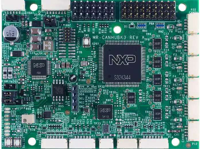
NXP MR-CANHUBK3 [1] is an evaluation board for mobile robotics applications such as autonomous mobile robots (AMR) and automated guided vehicles (AGV). It features an NXP S32K344 [2] general-purpose automotive microcontroller based on an Arm Cortex-M7 core (Lock-Step).
Hardware
- NXP S32K344
Arm Cortex-M7 (Lock-Step), 160 MHz (Max.)
4 MB of program flash, with ECC
320 KB RAM, with ECC
Ethernet 100 Mbps, CAN FD, FlexIO, QSPI
12-bit 1 Msps ADC, 16-bit eMIOS timer
- Interfaces:
Console UART
6x CAN FD
100Base-T1 Ethernet
JST-GH connectors and I/O headers for I2C, SPI, GPIO, PWM, etc.
More information about the hardware and design resources can be found at NXP MR-CANHUBK3 [1] website.
Supported Features
The mr_canhubk3 board configuration supports the following hardware features:
Interface |
Controller |
Driver/Component |
|---|---|---|
SIUL2 |
on-chip |
pinctrl
gpio
external interrupt controller
|
WKPU |
on-chip |
interrupt controller |
LPUART |
on-chip |
serial |
QSPI |
on-chip |
flash |
FLEXCAN |
on-chip |
can |
LPI2C |
on-chip |
i2c |
ADC SAR |
on-chip |
adc |
LPSPI |
on-chip |
spi |
WDT |
FS26 SBC |
watchdog |
EMAC |
on-chip |
ethernet mdio |
eMIOS |
on-chip |
pwm |
EDMA |
on-chip |
dma |
The default configuration can be found in the Kconfig file boards/arm/mr_canhubk3/mr_canhubk3_defconfig.
Connections and IOs
Each GPIO port is divided into two banks: low bank, from pin 0 to 15, and high
bank, from pin 16 to 31. For example, PTA2 is the pin 2 of gpioa_l (low
bank), and PTA20 is the pin 4 of gpioa_h (high bank).
The GPIO controller provides the option to route external input pad interrupts to either the SIUL2 EIRQ or WKPU interrupt controllers, as supported by the SoC. By default, GPIO interrupts are routed to SIUL2 EIRQ interrupt controller, unless they are explicity configured to be directed to the WKPU interrupt controller, as outlined in dts/bindings/gpio/nxp,s32-gpio.yaml.
To find information about which GPIOs are compatible with each interrupt controller, refer to the device reference manual.
Note
It is important to highlight that the current board configuration lacks support for wake-up events and power-management features. WKPU functionality is restricted solely to serving as an interrupt controller.
LEDs
The MR-CANHUBK3 board has one user RGB LED:
Devicetree node |
Color |
Pin |
Pin Functions |
|---|---|---|---|
led0 / user_led1_red |
Red |
PTE14 |
FXIO D7 / EMIOS0 CH19 |
led1 / user_led1_green |
Green |
PTA27 |
FXIO D5 / EMIOS1 CH10 / EMIOS2 CH10 |
led2 / user_led1_blue |
Blue |
PTE12 |
FXIO D8 / EMIOS1 CH5 |
The user can control the LEDs in any way. An output of 0 illuminates the LED.
System Clock
The Arm Cortex-M7 (Lock-Step) are configured to run at 160 MHz.
Serial Console
By default, the serial console is provided through lpuart2 on the 7-pin
DCD-LZ debug connector P6.
Connector |
Pin |
Pin Function |
|---|---|---|
P6.2 |
PTA9 |
LPUART2_TX |
P6.3 |
PTA8 |
LPUART2_RX |
CAN
CAN is provided through FLEXCAN interface with 6 instances.
Devicetree node |
Pin |
Pin Function |
Bus Connector |
|---|---|---|---|
flexcan0 |
PTA6
PTA7
|
PTA6_CAN0_RX
PTA7_CAN0_TX
|
P12/P13 |
flexcan1 |
PTC9
PTC8
|
PTC9_CAN0_RX
PTC8_CAN0_TX
|
P14/P15 |
flexcan2 |
PTE25
PTE24
|
PTE25_CAN0_RX
PTE24_CAN0_TX
|
P16/P17 |
flexcan3 |
PTC29
PTC28
|
PTC29_CAN0_RX
PTC28_CAN0_TX
|
P18/019 |
flexcan4 |
PTC31
PTC30
|
PTC31_CAN0_RX
PTC30_CAN0_TX
|
P20/P21 |
flexcan5 |
PTC11
PTC10
|
PTC11_CAN0_RX
PTC10_CAN0_TX
|
P22/P23 |
Note
There is limitation by HAL SDK, so CAN only has support maximum 64 message buffers (MBs) and support maximum 32 message buffers for concurrent active instances with 8 bytes payload. We need to pay attention to configuration options:
CONFIG_CAN_MAX_MBmust be less or equal than the maximum number of message buffers that is according to the table below.CONFIG_CAN_MAX_FILTERmust be less or equal thanCONFIG_CAN_MAX_MB.
Devicetree node |
Payload |
Hardware support |
Software support |
|---|---|---|---|
flexcan0 |
8 bytes
16 bytes
32 bytes
64 bytes
|
96 MBs
63 MBs
36 MBs
21 MBs
|
64 MBs
42 MBs
24 MBs
14 MBs
|
flexcan1 |
8 bytes
16 bytes
32 bytes
64 bytes
|
64 MBs
42 MBs
24 MBs
14 MBs
|
64 MBs
42 MBs
24 MBs
14 MBs
|
flexcan2 |
8 bytes
16 bytes
32 bytes
64 bytes
|
64 MBs
42 MBs
24 MBs
14 MBs
|
64 MBs
42 MBs
24 MBs
14 MBs
|
flexcan3 |
8 bytes
16 bytes
32 bytes
64 bytes
|
32 MBs
21 MBs
12 MBs
7 MBs
|
32 MBs
21 MBs
12 MBs
7 MBs
|
flexcan4 |
8 bytes
16 bytes
32 bytes
64 bytes
|
32 MBs
21 MBs
12 MBs
7 MBs
|
32 MBs
21 MBs
12 MBs
7 MBs
|
flexcan5 |
8 bytes
16 bytes
32 bytes
64 bytes
|
32 MBs
21 MBs
12 MBs
7 MBs
|
32 MBs
21 MBs
12 MBs
7 MBs
|
Note
A CAN bus usually requires 60 Ohm termination at both ends of the bus. This may be
accomplished using one of the included CAN termination boards. For more details, refer
to the section 6.3 CAN Connectors in the Hardware User Manual of NXP MR-CANHUBK3 [1].
I2C
I2C is provided through LPI2C interface with 2 instances lpi2c0 and lpi2c1
on corresponding connectors P4, P3.
Connector |
Pin |
Pin Function |
|---|---|---|
P3.2 |
PTD9 |
LPI2C1_SCL |
P3.3 |
PTD8 |
LPI2C1_SDA |
P4.3 |
PTD14 |
LPI2C0_SCL |
P4.4 |
PTD13 |
LPI2C0_SDA |
ADC
ADC is provided through ADC SAR controller with 3 instances. ADC channels are divided into 3 groups (precision, standard and external).
Note
All channels of an instance only run on 1 group channel at the same time.
FS26 SBC Watchdog
On normal operation after the board is powered on, there is a window of 256 ms on which the FS26 watchdog must be serviced with a good token refresh, otherwise the watchdog will signal a reset to the MCU. This board configuration enables the FS26 watchdog driver that handles this initialization.
Note
The FS26 can also be started in debug mode (watchdog disabled) following these steps:
Power off the board.
Remove the jumper
JP1(pins 1-2 open), which is connected by default.Power on the board.
Reconnect the jumper
JP1(pins 1-2 shorted).
External Flash
The on-board MX25L6433F 64M-bit multi-I/O Serial NOR Flash memory is connected to the QSPI controller port A1. This board configuration selects it as the default flash controller.
Ethernet
This board has a single instance of Ethernet Media Access Controller (EMAC) interfacing with a NXP TJA1103 [4] 100Base-T1 Ethernet PHY. Currently, there is limited driver for this PHY that allows for overiding the default pin strapping configuration for the PHY (RMII, master, autonomous mode enabled, polarity correction enabled) to slave mode.
The 100Base-T1 signals are available in connector P9 and can be converted to
100Base-T using a Ethernet media converter such as RDDRONE-T1ADAPT [5].
Programming and Debugging
Applications for the mr_canhubk3 board can be built in the usual way as
documented in Building an Application.
This board configuration supports Lauterbach TRACE32 [6] and SEGGER J-Link [7] West runners for flashing and debugging applications. Follow the steps described in Lauterbach TRACE32 Debug Host Tools and J-Link Debug Host Tools, to setup the flash and debug host tools for these runners, respectively. The default runner is J-Link.
Flashing
Run the west flash command to flash the application using SEGGER J-Link.
Alternatively, run west flash -r trace32 to use Lauterbach TRACE32.
The Lauterbach TRACE32 runner supports additional options that can be passed through command line:
west flash -r trace32 --startup-args elfFile=<elf_path> loadTo=<flash/sram>
   eraseFlash=<yes/no> verifyFlash=<yes/no>
Where:
<elf_path>is the path to the Zephyr application ELF in the output directoryloadTo=flashloads the application to the SoC internal program flash (CONFIG_XIPmust be set), andloadTo=sramload the application to SRAM. Default isflash.eraseFlash=yeserases the whole content of SoC internal flash before the application is downloaded to either Flash or SRAM. This routine takes time to execute. Default isno.verifyFlash=yesverify the SoC internal flash content after programming (use together withloadTo=flash). Default isno.
For example, to erase and verify flash content:
west flash -r trace32 --startup-args elfFile=build/zephyr/zephyr.elf loadTo=flash eraseFlash=yes verifyFlash=yes
Debugging
Run the west debug command to start a GDB session using SEGGER J-Link.
Alternatively, run west debug -r trace32 to launch the Lauterbach TRACE32
software debugging interface.