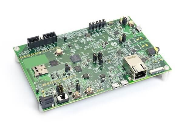
NXP MIMXRT1050-EVK
Overview
The i.MX RT1050 is a new processor family featuring NXP’s advanced implementation of the ARM Cortex-M7 Core. It provides high CPU performance and real-time response.
The i.MX RT1050 provides various memory interfaces, including SDRAM, Raw NAND FLASH, NOR FLASH, SD/eMMC, Quad SPI, HyperBus and a wide range of other interfaces for connecting peripherals, such as WLAN, Bluetooth™, GPS, displays, and camera sensors. As with other i.MX processors, i.MX RT1050 also has rich audio and video features, including LCD display, basic 2D graphics, camera interface, SPDIF, and I2S audio interface.
The following document refers to the discontinued MIMXRT1050-EVK board. For the MIMXRT1050-EVKB board, refer to Board Revisions section.
Hardware
MIMXRT1052DVL6A MCU (600 MHz, 512 KB TCM)
Memory
256 KB SDRAM
64 Mbit QSPI Flash
512 Mbit Hyper Flash
Display
LCD connector
Touch connector
Ethernet
10/100 Mbit/s Ethernet PHY
USB
USB 2.0 OTG connector
USB 2.0 host connector
Audio
3.5 mm audio stereo headphone jack
Board-mounted microphone
Left and right speaker out connectors
Power
5 V DC jack
Debug
JTAG 20-pin connector
OpenSDA with DAPLink
Sensor
FXOS8700CQ 6-axis e-compass
CMOS camera sensor interface
Expansion port
Arduino interface
CAN bus connector
For more information about the MIMXRT1050 SoC and MIMXRT1050-EVK board, see these references:
External Memory
This platform has the following external memories:
Device |
Controller |
Status |
|---|---|---|
IS42S16160J |
SEMC |
Enabled via device configuration data block, which sets up SEMC at boot time |
S26KS512SDPBHI020 |
FLEXSPI |
Enabled via flash configurationn block, which sets up FLEXSPI at boot time. |
Supported Features
The mimxrt1050_evk board configuration supports the hardware features listed below. For additional features not yet supported, please also refer to the NXP MIMXRT1064-EVK , which is the superset board in NXP’s i.MX RT10xx family. NXP prioritizes enabling the superset board with NXP’s Full Platform Support for Zephyr. Therefore, the mimxrt1064_evk board may have additional features already supported, which can also be re-used on this mimxrt1050_evk board:
Interface |
Controller |
Driver/Component |
|---|---|---|
NVIC |
on-chip |
nested vector interrupt controller |
SYSTICK |
on-chip |
systick |
DISPLAY |
on-chip |
display |
GPIO |
on-chip |
gpio |
I2C |
on-chip |
i2c |
SDHC |
on-chip |
disk access |
SPI |
on-chip |
spi |
UART |
on-chip |
serial port-polling; serial port-interrupt |
ENET |
on-chip |
ethernet |
USB |
on-chip |
USB device |
ADC |
on-chip |
adc |
GPT |
on-chip |
gpt |
TRNG |
on-chip |
entropy |
FLEXSPI |
on-chip |
flash programming |
The default configuration can be found in the defconfig file:
boards/arm/mimxrt1050_evk/mimxrt1050_evk_defconfig
Other hardware features are not currently supported by the port.
Connections and IOs
The MIMXRT1050 SoC has five pairs of pinmux/gpio controllers.
Name |
Function |
Usage |
|---|---|---|
GPIO_AD_B0_00 |
LPSPI1_SCK |
SPI |
GPIO_AD_B0_01 |
LPSPI1_SDO |
SPI |
GPIO_AD_B0_02 |
LPSPI3_SDI/LCD_RST| SPI/LCD Display |
|
GPIO_AD_B0_03 |
LPSPI3_PCS0 |
SPI |
GPIO_AD_B0_05 |
GPIO |
SD Card |
GPIO_AD_B0_09 |
GPIO/ENET_RST |
LED |
GPIO_AD_B0_10 |
GPIO/ENET_INT |
GPIO/Ethernet |
GPIO_AD_B0_11 |
GPIO |
Touch Interrupt |
GPIO_AD_B0_12 |
LPUART1_TX |
UART Console |
GPIO_AD_B0_13 |
LPUART1_RX |
UART Console |
GPIO_AD_B1_00 |
LPI2C1_SCL |
I2C |
GPIO_AD_B1_01 |
LPI2C1_SDA |
I2C |
GPIO_AD_B1_06 |
LPUART3_TX |
UART BT HCI |
GPIO_AD_B1_07 |
LPUART3_RX |
UART BT HCI |
GPIO_AD_B1_11 |
ADC |
ADC1 channel 0 |
WAKEUP |
GPIO |
SW0 |
GPIO_B0_00 |
LCD_CLK |
LCD Display |
GPIO_B0_01 |
LCD_ENABLE |
LCD Display |
GPIO_B0_02 |
LCD_HSYNC |
LCD Display |
GPIO_B0_03 |
LCD_VSYNC |
LCD Display |
GPIO_B0_04 |
LCD_DATA00 |
LCD Display |
GPIO_B0_05 |
LCD_DATA01 |
LCD Display |
GPIO_B0_06 |
LCD_DATA02 |
LCD Display |
GPIO_B0_07 |
LCD_DATA03 |
LCD Display |
GPIO_B0_08 |
LCD_DATA04 |
LCD Display |
GPIO_B0_09 |
LCD_DATA05 |
LCD Display |
GPIO_B0_10 |
LCD_DATA06 |
LCD Display |
GPIO_B0_11 |
LCD_DATA07 |
LCD Display |
GPIO_B0_12 |
LCD_DATA08 |
LCD Display |
GPIO_B0_13 |
LCD_DATA09 |
LCD Display |
GPIO_B0_14 |
LCD_DATA10 |
LCD Display |
GPIO_B0_15 |
LCD_DATA11 |
LCD Display |
GPIO_B1_00 |
LCD_DATA12 |
LCD Display |
GPIO_B1_01 |
LCD_DATA13 |
LCD Display |
GPIO_B1_02 |
LCD_DATA14 |
LCD Display |
GPIO_B1_03 |
LCD_DATA15 |
LCD Display |
GPIO_B1_04 |
ENET_RX_DATA00 |
Ethernet |
GPIO_B1_05 |
ENET_RX_DATA01 |
Ethernet |
GPIO_B1_06 |
ENET_RX_EN |
Ethernet |
GPIO_B1_07 |
ENET_TX_DATA00 |
Ethernet |
GPIO_B1_08 |
ENET_TX_DATA01 |
Ethernet |
GPIO_B1_09 |
ENET_TX_EN |
Ethernet |
GPIO_B1_10 |
ENET_REF_CLK |
Ethernet |
GPIO_B1_11 |
ENET_RX_ER |
Ethernet |
GPIO_B1_12 |
GPIO |
SD Card |
GPIO_B1_14 |
USDHC1_VSELECT |
SD Card |
GPIO_B1_15 |
BACKLIGHT_CTL |
LCD Display |
GPIO_EMC_40 |
ENET_MDC |
Ethernet |
GPIO_EMC_41 |
ENET_MDIO |
Ethernet |
GPIO_AD_B0_09 |
ENET_RST |
Ethernet |
GPIO_AD_B0_10 |
ENET_INT |
Ethernet |
GPIO_SD_B0_00 |
USDHC1_CMD/LPSPI1_SCK | SD Card/SPI |
|
GPIO_SD_B0_01 |
USDHC1_CLK/LPSPI1_PCS0 | SD Card/SPI |
|
GPIO_SD_B0_02 |
USDHC1_DATA0/LPSPI1_SDO | SD Card/SPI |
|
GPIO_SD_B0_03 |
USDHC1_DATA1/LPSPI1_SDI | SD Card/SPI |
|
GPIO_SD_B0_04 |
USDHC1_DATA2 |
SD Card |
GPIO_SD_B0_05 |
USDHC1_DATA3 |
SD Card |
GPIO_AD_B1_02 |
1588_EVENT2_OUT |
1588 |
GPIO_AD_B1_03 |
1588_EVENT2_IN |
1588 |
Note
In order to use the SPI peripheral on this board, resistors R278, R279, R280, and R281 must be populated with zero ohm resistors
System Clock
The MIMXRT1050 SoC is configured to use SysTick as the system clock source, running at 600MHz.
When power management is enabled, the 32 KHz low frequency oscillator on the board will be used as a source for the GPT timer to generate a system clock. This clock enables lower power states, at the cost of reduced resolution
Serial Port
The MIMXRT1050 SoC has eight UARTs. LPUART1 is configured for the console,
LPUART3 for the Bluetooth Host Controller Interface (BT HCI), and the
remaining are not used.
USB
The RT1050 SoC has two USB OTG (USBOTG) controllers that supports both device and host functions through its micro USB connectors. Only USB device function is supported in Zephyr at the moment.
Programming and Debugging
Build and flash applications as usual (see Building an Application and Run an Application for more details).
Configuring a Debug Probe
A debug probe is used for both flashing and debugging the board. This board is configured by default to use the OpenSDA DAPLink Onboard Debug Probe, however the pyOCD Debug Host Tools do not yet support programming the external flashes on this board so you must reconfigure the board for one of the following debug probes instead.
Using LinkServer
Install the LinkServer Debug Host Tools and make sure they are in your search path. LinkServer works with the default CMSIS-DAP firmware included in the on-board debugger.
Linkserver is the default runner. You may also se the -r linkserver option
with West to use the LinkServer runner.
west flash
west debug
JLink (on-board): OpenSDA J-Link Onboard Debug Probe
Install the J-Link Debug Host Tools and make sure they are in your search path.
Follow the instructions in OpenSDA J-Link Onboard Debug Probe to program the OpenSDA J-Link MIMXRT1050-EVK-Hyperflash Firmware. Check that jumpers J32 and J33 are on (they are on by default when boards ship from the factory) to ensure SWD signals are connected to the OpenSDA microcontroller.
Follow the instructions in Enable QSPI flash support in SEGGER JLink in order to support your EVK if you have modified it to boot from QSPI NOR flash as specified by NXP AN12108.
External JLink J-Link External Debug Probe
Install the J-Link Debug Host Tools and make sure they are in your search path.
Attach a J-Link 20-pin connector to J21. Check that jumpers J32 and J33 are off (they are on by default when boards ship from the factory) to ensure SWD signals are disconnected from the OpenSDA microcontroller.
Configuring a Console
Regardless of your choice in debug probe, we will use the OpenSDA microcontroller as a usb-to-serial adapter for the serial console. Check that jumpers J30 and J31 are on (they are on by default when boards ship from the factory) to connect UART signals to the OpenSDA microcontroller.
Connect a USB cable from your PC to J28.
Use the following settings with your serial terminal of choice (minicom, putty, etc.):
Speed: 115200
Data: 8 bits
Parity: None
Stop bits: 1
Flashing
Here is an example for the Hello World application.
# From the root of the zephyr repository
west build -b mimxrt1050_evk samples/hello_world
west flash
Open a serial terminal, reset the board (press the SW4 button), and you should see the following message in the terminal:
***** Booting Zephyr OS v1.14.0-rc1 *****
Hello World! mimxrt1050_evk
Debugging
Here is an example for the Hello World application.
# From the root of the zephyr repository
west build -b mimxrt1050_evk samples/hello_world
west debug
Open a serial terminal, step through the application in your debugger, and you should see the following message in the terminal:
***** Booting Zephyr OS v1.14.0-rc1 *****
Hello World! mimxrt1050_evk
Troubleshooting
If the debug probe fails to connect with the following error, it’s possible
that the boot header in HyperFlash is invalid or corrupted. The boot header is
configured by CONFIG_NXP_IMX_RT_BOOT_HEADER.
Remote debugging using :2331
Remote communication error.  Target disconnected.: Connection reset by peer.
"monitor" command not supported by this target.
"monitor" command not supported by this target.
You can't do that when your target is `exec'
(gdb) Could not connect to target.
Please check power, connection and settings.
You can fix it by erasing and reprogramming the HyperFlash with the following steps:
Set the SW7 DIP switches to ON-ON-ON-OFF to prevent booting from HyperFlash.
Reset by pressing SW4
Run
west debugorwest flashagain with a known working Zephyr application.Set the SW7 DIP switches to OFF-ON-ON-OFF to boot from HyperFlash.
Reset by pressing SW4
Board Revisions
The original MIMXRT1050-EVK (rev A0) board was updated with a newer MIMXRT1050-EVKB (rev A1) board, with these major hardware differences:
SoC changed from MIMXRT1052DVL6A to MIMXRT1052DVL6B
Hardware bug fixes for: power, interfaces, and memory
Arduino headers included
For more details, please see the following NXP i.MXRT1050 A0 to A1 Migration Guide.
Current Zephyr build supports the new MIMXRT1050-EVKB
Experimental ENET Driver
Current default ethernet driver is eth_mcux, with binding nxp,kinetis-ethernet. There is a new driver with binding nxp,enet, which is experimental and undergoing development, but will have enhanced capability, such as not hardcoding code for only one phy in the driver like eth_mcux.
To build for this EVK with the new driver, include the experimental overlay to west build with the option -DEXTRA_DTC_OVERLAY_FILE=nxp,enet-experimental.overlay.