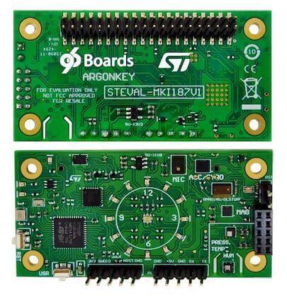
96Boards Argonkey
Overview
96Boards Argonkey board is based on the ST Microelectronics STM32F412CG Cortex M4 CPU.
This board acts as a sensor hub platform for all 96Boards compliant family products. It can also be used as a standalone board.
96Boards Argonkey
Hardware
96Boards Argonkey provides the following hardware components:
STM32F412CG in UFQFPN48 package
ARM® 32-bit Cortex®-M4 CPU with FPU
100 MHz max CPU frequency
1.8V work voltage
1024 KB Flash
256 KB SRAM
On board sensors:
Humidity: STMicro HTS221
Temperature/Pressure: STMicro LPS22HB
ALS: Intersil ISL29034
Proximity: STMicro VL53L0X
Accelerometer/Gyroscope: STMicro LSM6DSL
Geomagnetic: STMicro LIS2MDL
AMR Hall sensor: MRMS501A
Microphone: STMicro MP34DT05
2 User LEDs
16 General purpose LEDs
GPIO with external interrupt capability
UART
I2C (3)
SPI (1)
I2S (1)
Supported Features
The Zephyr 96b_argonkey board configuration supports the following hardware features:
Interface |
Controller |
Driver/Component |
|---|---|---|
NVIC |
on-chip |
nested vector interrupt controller |
SYSTICK |
on-chip |
system clock |
UART |
on-chip |
serial port |
GPIO |
on-chip |
gpio |
PINMUX |
on-chip |
pinmux |
FLASH |
on-chip |
flash |
SPI |
on-chip |
spi |
I2C |
on-chip |
i2c |
More information about the board can be found at the ARGONKEY website [1].
The default board configuration can be found in the defconfig file:
boards/arm/96b_argonkey/96b_argonkey_defconfig
Connections and IOs
LED
LED1 / User1 LED = PB2
LED2 / User2 LED = PC13
System Clock
96Boards Argonkey can be driven by an internal oscillator as well as the main PLL clock. In default board configuration, the 16MHz external oscillator is used to drive the main PLL clock to generate a System Clock (SYSCLK) at 84MHz. On the bus side, AHB clock runs at 84MHz, while APB1/APB2 clock runs at 42MHz.
Serial Port
On 96Boards Argonkey, Zephyr console output is assigned to USART1. Default settings are 115200 8N1.
I2C
96Boards Argonkey board has up to 3 I2Cs. The default I2C mapping is:
I2C1_SCL : PB6
I2C1_SDA : PB7
I2C2_SCL : PB10
I2C2_SDA : PB9
I2C3_SCL : PA8
I2C3_SCL : PB4
I2C3 goes to the P2 connector and can be used to attach external sensors. It goes to 100Kbit maximum.
SPI
96Boards Argonkey board has 2 SPIs. SPI1 is used in slave mode as the communication bus with the AP. SPI2 is used in master mode to control the LSM6DSL sensor. The default SPI mapping is:
SPI1_NSS : PA4
SPI1_SCK : PA5
SPI1_MISO : PA6
SPI1_MOSI : PA7
SPI2_NSS : PB12
SPI2_SCK : PB13
SPI2_MISO : PB14
SPI2_MOSI : PB15
Programming and Debugging
Building
Here is an example for building the Hello World application.
# From the root of the zephyr repository
west build -b 96b_argonkey samples/hello_world
Flashing
96Boards Argonkey can be flashed by two methods, one using the ROM bootloader and another using the SWD debug port (which requires additional hardware).
Flashing using the ROM bootloader requires a special activation pattern, which can be triggered by using the BOOT0 pin. The ROM bootloader supports flashing via USB (DFU), UART, I2C and SPI, but this document describes the UART case only. You can read more about how to enable and use the ROM bootloader by checking the application note AN2606 [2] .
Using ROM bootloader:
Hereafter the documents describes basic steps to perform ArgonKey firmware flashing on a Linux PC using UART as communication channel.
Connect ArgonKey UART to your Linux PC using, for example, a USB-TTL serial cable. The flashing procedure has been tested using a TTL-232RG [5] cable with FTDI chip. The UART pins on ArgonKey can be found on the P3 low speed expansion connector on the back of the board.
GND (black) to ArgonKey GND (P3.1)
TXD (orange) to ArgonKey UART0_TXD (P3.5)
RXD (yellow) to ArgonKey UART0_RXD (P3.7)
When the USB cable is inserted to the Linux PC the following device will be created: /dev/ttyUSBx (x is usually ‘0’).
Force STM32F412CG to enter in Bootloader mode
Connect BOOT0 to 1V8 (link P2.1 to P3.30)
Press and release the RST button
Use stm32flash utility to flash the ArgonKey:
$ stm32flash -w zephyr.bin -v -g 0x08000000 /dev/ttyUSB0
See References section for more info on stm32flash [3].
Using SWD debugger:
Select a commercial JTAG/SWD h/w tool and connect it to ArgonKey P4 connector.
The ArgonKey has been tested using the ST-LINK/V2 [4] tool. Once that the tool is connected to the PC through USB, it presents itself as a USB composite device with mass storage capability. The device can be then mounted in linux and the f/w can be actually copied there and will be automatically flashed by the ST-LINK onto the ArgonKey.
Example:
$ mount /dev/sdb /mnt
$ cp zephyr.bin /mnt
$ umount /mnt