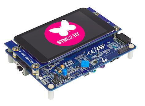
ST STM32H747I Discovery
Overview
The discovery kit enables a wide diversity of applications taking benefit from audio, multi-sensor support, graphics, security, video, and high-speed connectivity features.
The board includes an STM32H747XI SoC with a high-performance DSP, Arm Cortex-M7 + Cortex-M4 MCU, with 2MBytes of Flash memory, 1MB RAM, 480 MHz CPU, Art Accelerator, L1 cache, external memory interface, large set of peripherals, SMPS, and MIPI-DSI.
Additionally, the board features:
On-board ST-LINK/V3E supporting USB reenumeration capability
USB ST-LINK functions: virtual COM port, mass storage, debug port
Flexible power-supply options:
ST-LINK USB VBUS, USB OTG HS connector, or external sources
4” capacitive touch LCD display module with MIPI® DSI interface
Ethernet compliant with IEEE802.3-2002
USB OTG HS
Stereo speaker outputs
ST-MEMS digital microphones
2 x 512-Mbit QUAD-SPI NOR Flash memory
256-Mbit SDRAM
4 color user LEDs
1 user and reset push-button
4-direction joystick with selection button
Arduino Uno V3 connectors
More information about the board can be found at the STM32H747I-DISCO website. More information about STM32H747XIH6 can be found here:
Supported Features
The current Zephyr stm32h747i_disco board configuration supports the following hardware features:
Interface |
Controller |
Driver/Component |
|---|---|---|
NVIC |
on-chip |
nested vector interrupt controller |
UART |
on-chip |
serial port-polling; serial port-interrupt |
PINMUX |
on-chip |
pinmux |
GPIO |
on-chip |
gpio |
FLASH |
on-chip |
flash memory |
ETHERNET |
on-chip |
ethernet (*) |
RNG |
on-chip |
True Random number generator |
FMC |
on-chip |
memc (SDRAM) |
SPI |
on-chip |
spi |
QSPI NOR |
on-chip |
off-chip flash |
SDMMC |
on-chip |
disk access |
IPM |
on-chip |
virtual mailbox based on HSEM |
DISPLAY |
on-chip |
MIPI DSI Host with shield (MP1166) st_b_lcd40_dsi1_mb1166 |
- (*) From UM2411 Rev 4:
With the default setting, the Ethernet feature is not working because of a conflict between ETH_MDC and SAI4_D1 of the MEMs digital microphone. Make sure you have SB8 closed and SB21 open to get Ethernet working.
Other hardware features are not yet supported on Zephyr porting.
The default configuration per core can be found in the defconfig files:
boards/arm/stm32h747i_disco/stm32h747i_disco_defconfig_m7 and
boards/arm/stm32h747i_disco/stm32h747i_disco_defconfig_m4
Pin Mapping
STM32H747I Discovery kit has 9 GPIO controllers. These controllers are responsible for pin muxing, input/output, pull-up, etc.
For more details please refer to STM32H747I-DISCO website.
Default Zephyr Peripheral Mapping:
UART_1 TX/RX : PA9/PA10 (ST-Link Virtual Port Com)
UART_8 TX/RX : PJ8/PJ9 (Arduino Serial)
SPI_5 NSS/SCK/MISO/MOSI : PK1/PK0/PJ11/PJ10 (Arduino SPI)
SDMMC_1 D0/D1/D2/D3/CK/CMD: PC8/PC9/PC10/PC11/PC12/PD2
LD1 : PI12
LD2 : PI13
LD3 : PI14
LD4 : PI15
W-UP : PC13
J-CENTER : PK2
J-DOWN : PK3
J-LEFT : PK4
J-RIGHT : PK5
J-UP : PK6
System Clock
The STM32H747I System Clock can be driven by an internal or external oscillator, as well as by the main PLL clock. By default, the CPU1 (Cortex-M7) System clock is driven by the PLL clock at 400MHz, and the CPU2 (Cortex-M4) System clock is driven at 200MHz. PLL clock is feed by a 25MHz high speed external clock.
Serial Port
The STM32H747I Discovery kit has up to 8 UARTs. Default configuration assigns USART1 and UART8 to the CPU1. The Zephyr console output is assigned to UART1 which connected to the onboard ST-LINK/V3.0. Virtual COM port interface. Default communication settings are 115200 8N1.
Ethernet
Disclaimer: This section is mostly copy-paste of corresponding DISCO_H747I modifications for Ethernet mbed blog post. The author of this article sincerely allowed to use the images and his knowledge about necessary HW modifications to get Ethernet working with this board.
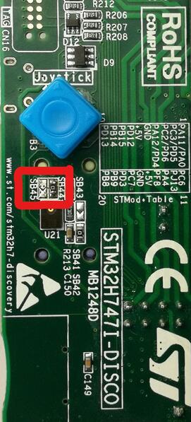
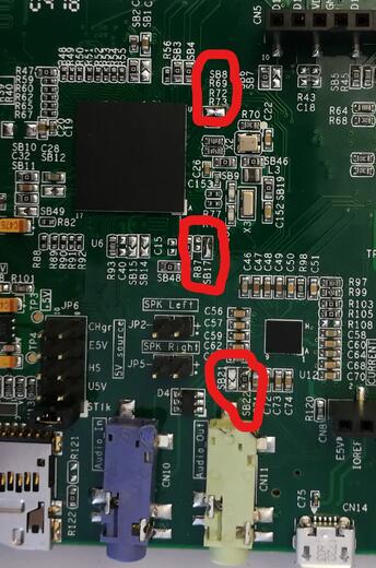
To get Ethernet working following HW modifications are required:
SB21, SB45 and R87 should be opened
SB22, SB44, SB17 and SB8 should be closed
Following two images shows necessary changes on the board marked:
Display
The STM32H747I Discovery kit has a dedicated DSI LCD connector CN15, where
the MB1166 (B-LCD40-DSI1) display extension board can be mounted. Enable display
support in Zephyr by adding the shield st_b_lcd40_dsi1_mb1166 to your build
command, for example:
# From the root of the zephyr repository
west build -b stm32h747i_disco_m7 samples/drivers/display -- -DSHIELD=st_b_lcd40_dsi1_mb1166
west flash
Note
Currently only the older version MB1166-A03 is supported by Zephyr. The newer version MB1166-A09 does not get initialized correctly (see GitHub #60888).
Resources sharing
The dual core nature of STM32H747 SoC requires sharing HW resources between the two cores. This is done in 3 ways:
Compilation: Clock configuration is only accessible to M7 core. M4 core only has access to bus clock activation and deactivation.
Static pre-compilation assignment: Peripherals such as a UART are assigned in devicetree before compilation. The user must ensure peripherals are not assigned to both cores at the same time.
Run time protection: Interrupt-controller and GPIO configurations could be accessed by both cores at run time. Accesses are protected by a hardware semaphore to avoid potential concurrent access issues.
Programming and Debugging
Applications for the stm32h747i_disco board should be built per core target,
using either stm32h747i_disco_m7 or `stm32h747i_disco_m4 as the target.
See Building an Application for more information about application builds.
Note
If using OpenOCD you will need a recent development version as the last official release does not support H7 dualcore yet. Also, with OpenOCD, sometimes, flashing is not working. It is necessary to erase the flash (with STM32CubeProgrammer for example) to make it work again. Debugging with OpenOCD is currently working for this board only with Cortex M7, not Cortex M4.
Flashing
Flashing operation will depend on the target to be flashed and the SoC
option bytes configuration.
It is advised to use STM32CubeProgrammer to check and update option bytes
configuration and flash stm32h747i_disco_m7 and stm32h747i_disco_m4 targets.
By default:
CPU1 (Cortex-M7) boot address is set to 0x80000000 (OB: BOOT_CM7_ADD0)
CPU2 (Cortex-M4) boot address is set to 0x81000000 (OB: BOOT_CM4_ADD0)
Also, default out of the box board configuration enables CM7 and CM4 boot when board is powered (Option bytes BCM7 and BCM4 are checked). It is possible to change Option Bytes so that CM7 boots first in stand alone, and CM7 will wakeup CM4 after clock initialization. Drivers are able to take into account both Option Bytes configurations automatically.
Zephyr flash configuration has been set to meet these default settings.
Alternatively, west STM32CubeProgrammer runner can be used, after installing it, to flash applications for both cores. The target core is detected automatically.
$ west flash --runner stm32cubeprogrammer
Flashing an application to STM32H747I M7 Core
First, connect the STM32H747I Discovery kit to your host computer using the USB port to prepare it for flashing. Then build and flash your application.
Here is an example for the Hello World application.
# From the root of the zephyr repository
west build -b stm32h747i_disco_m7 samples/hello_world
west flash
Run a serial host program to connect with your board:
$ minicom -D /dev/ttyACM0
You should see the following message on the console:
Hello World! stm32h747i_disco_m7
Note
Sometimes, flashing is not working. It is necessary to erase the flash (with STM32CubeProgrammer for example) to make it work again.
Similarly, you can build and flash samples on the M4 target. For this, please take care of the resource sharing (UART port used for console for instance).
Here is an example for the Blinky application on M4 core.
# From the root of the zephyr repository
west build -b stm32h747i_disco_m4 samples/basic/blinky
west flash
Debugging
You can debug an application in the usual way. Here is an example for the Hello World application.
# From the root of the zephyr repository
west build -b stm32h747i_disco_m7 samples/hello_world
west debug
Debugging with west is currently not available on Cortex M4 side. In order to debug a Zephyr application on Cortex M4 side, you can use STM32CubeIDE.