OLIMEX-STM32-H103
Overview
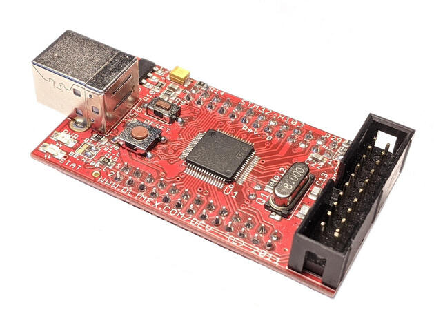
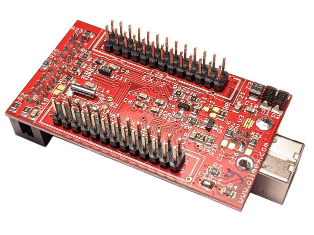
The OLIMEX-STM32-H103 is a simple development board based on the STMicroelectronics STM32F103RBT6 ARM Cortex-M3 CPU, with all the MCU pins populated and accessible through two male 26-pin connectors.
OLIMEX-STM32-H103
Hardware
Information about the board can be found at the OLIMEX-STM32-H103 website and OLIMEX-STM32-H103 user manual. The OLIMEX-STM32-H103 schematic is also available.
The ST STM32F103RB Datasheet contains the processor’s information and the datasheet.
Supported Features
The OLIMEX STM32-H103 supports the following hardware features:
Interface |
Controller |
Driver/Component |
|---|---|---|
NVIC |
on-chip |
nested vectored interrupt controller |
SYSTICK |
on-chip |
system clock |
UART |
on-chip |
serial port |
GPIO |
on-chip |
gpio |
I2C |
on-chip |
i2c |
PWM |
on-chip |
pwm |
SPI |
on-chip |
spi |
USB |
on-chip |
USB device |
ADC |
on-chip |
adc |
Other hardware features have not been enabled yet for this board.
Connections and IOs
System Clock
The on-board 8 MHz crystal is used to produce a 72 MHz system clock with PLL.
Zephyr Console
UART2 is used as Zephyr’s console. Default settings are 115200 8N1.
On-Board LEDs
The board has one on-board green LED that is connected to PC12, which is active low.
There is also a red power LED neither connected nor controlled by the MCU.
USB
USB is not enabled by default.
PC4 can be configured as a GPIO input to detect power on the USB port. It is possible to disconnect it by desoldering the appropriate pad in the PCB.
PC11 can be used to disconnect the pull-up resistor on the USB-DP line by setting it high.
External Connectors
JTAG/SWD debug
PIN # |
Signal Name |
PIN # |
Signal Name |
|---|---|---|---|
1 |
TVCC +3.3V |
2 |
TVCC 3.3V |
3 |
PB4 / TRST |
4 |
GND |
5 |
PA15 / TDI |
6 |
GND |
7 |
PA13 / TMS / SWDIO |
8 |
GND |
9 |
PA14 / TCK / SWCLK |
10 |
GND |
11 |
NC |
12 |
GND |
13 |
PB3 / TDO |
14 |
GND |
15 |
RST |
16 |
GND |
17 |
NC |
18 |
GND |
19 |
NC |
20 |
GND |
EXTENSION 1
PIN # |
Name / STM32F103 Port |
PIN # |
Name / STM32F103 Port |
|---|---|---|---|
1 |
PA11 / USB_DM |
2 |
PA8 |
3 |
PA12 / USB_DP |
4 |
PA9 |
5 |
+3.3V |
6 |
GND |
7 |
PA10 |
8 |
PC10 |
9 |
PC11 / USB_DISC |
10 |
PC12 / LED |
11 |
PD2 |
12 |
PB5 |
13 |
PB6 |
14 |
PA6 |
15 |
PB7 |
16 |
PB8 |
17 |
PB9 |
18 |
PA5 |
19 |
PC0 |
20 |
PC1 |
21 |
PB0 |
22 |
PA7 |
23 |
VBAT |
24 |
PC13 |
25 |
RST |
26 |
PB1 |
EXTENSION 2
PIN # |
Name / STM32F103 Port |
PIN # |
Name / STM32F103 Port |
|---|---|---|---|
1 |
VDDA |
2 |
PC2 |
3 |
GNDA |
4 |
PA0 / BUTTON |
5 |
+3.3V |
6 |
GND |
7 |
PA2 / USART2_TX |
8 |
PA1 |
9 |
PC3 |
10 |
PA3 / USART2_RX |
11 |
PA4 |
12 |
PC4 / USB_POWER |
13 |
PC5 |
14 |
PB10 |
15 |
P11 |
16 |
PB13 |
17 |
PB12 |
18 |
PB14 |
19 |
PB15 |
20 |
PC6 |
21 |
PC7 |
22 |
PC8 |
23 |
+5V USB |
24 |
PC9 |
25 |
GND |
26 |
VIN |
Programming and Debugging
This board does not include any embedded debug tool interface, instead you will have to use an external probe connected to the available 20-pin JTAG connector to program and debug the board. Both JTAG and SWD are supported.
By default when using west debug ST-Link will be used with OpenOCD’s
SWD transport, but it is also possible to use JTAG with the Olimex ARM-USB-OCD-H
probe, for instance. For the latter, you should replace the file openocd.cfg
by openocd_olimex_jtag.cfg, located in the board’s support directory.
The blackmagicprobe can also be used to program the device.
Flashing
Here is an example for the Button application.
# From the root of the zephyr repository
west build -b olimex_stm32_h103 samples/basic/button
west flash
Debugging
You can debug an application in the usual way. Here is an example for the Hello World application.
# From the root of the zephyr repository
west build -b olimex_stm32_h103 samples/hello_world
west debug