NXP LPCXPRESSO55S69
Overview
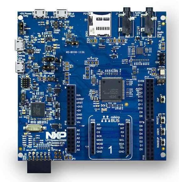
The LPCXpresso55S69 development board provides the ideal platform for evaluation of and development with the LPC55S6x MCU based on the Arm® Cortex®-M33 architecture. The board includes a high performance onboard debug probe, audio subsystem, and accelerometer, with several options for adding off-the-shelf add-on boards for networking, sensors, displays, and other interfaces.
Hardware
LPC55S69 dual core Arm Cortex-M33 microcontroller running at up to 100 MHz
Onboard, high-speed USB, Link2 debug probe with CMSIS-DAP and SEGGER J-Link protocol options
UART and SPI port bridging from LPC55S69 target to USB via the onboard debug probe
Hardware support for external debug probe
3 x user LEDs, plus Reset, ISP (3) and user buttons
Micro SD card slot (4-bit SDIO)
NXP MMA8652FCR1 accelerometer
Stereo audio codec with line in/out
High and full speed USB ports with micro A/B connector for host or device functionality
MikroEletronika Click expansion option
LPCXpresso-V3 expansion option compatible with Arduino UNO
PMod compatible expansion / host connector
For more information about the LPC55S69 SoC and LPCXPRESSO55S69 board, see:
Supported Features
NXP considers the LPCXpresso55S69 as the superset board for the LPC55xx series of MCUs. This board is a focus for NXP’s Full Platform Support for Zephyr, to better enable the entire LPC55xx series. NXP prioritizes enabling this board with new support for Zephyr features. The lpcxpresso55s69 board configuration supports the following hardware features:
Interface |
Controller |
Driver/Component |
|---|---|---|
NVIC |
on-chip |
nested vector interrupt controller |
SYSTICK |
on-chip |
systick |
IOCON |
on-chip |
pinmux |
GPIO |
on-chip |
gpio |
I2C |
on-chip |
i2c |
SPI |
on-chip |
spi |
USART |
on-chip |
serial port-polling; serial port-interrupt |
WWDT |
on-chip |
windowed watchdog timer |
TrustZone |
on-chip |
Trusted Firmware-M |
ADC |
on-chip |
adc |
CLOCK |
on-chip |
clock_control |
MAILBOX |
on-chip |
ipm |
HWINFO |
on-chip |
Unique device serial number |
USB HS |
on-chip |
USB High Speed device |
USB FS |
on-chip |
USB Full Speed device |
COUNTER |
on-chip |
counter |
I2S |
on-chip |
i2s |
PWM |
on-chip |
pwm |
RNG |
on-chip |
entropy; random |
IAP |
on-chip |
flash programming |
SDIF |
on-chip |
sdhc |
DMA |
on-chip |
dma (on CPU0) |
Targets available
The default configuration file
boards/arm/lpcxpresso55s69/lpcxpresso55s69_cpu0_defconfig
only enables the first core.
CPU0 is the only target that can run standalone.
lpcxpresso55s69_cpu0 secure (S) address space for CPU0
lpcxpresso55s69_ns non-secure (NS) address space for CPU0
lpcxpresso55s69_cpu1 CPU1 target, no security extensions
NS target for CPU0 does not work correctly without a secure image to configure
the system, then hand execution over to the NS environment. To enable a secure
image, run any of the tfm_integration samples. When using the NS target
CONFIG_BUILD_WITH_TFM is always enabled to ensure that a valid S image is
included during the build process.
CPU1 does not work without CPU0 enabling it.
To enable it, run one of the following samples in subsys\ipc:
- ipm_mcux
- openamp
Connections and IOs
The LPC55S69 SoC has IOCON registers, which can be used to configure the functionality of a pin.
Name |
Function |
Usage |
|---|---|---|
PIO0_26 |
SPI |
SPI MOSI |
PIO0_27 |
USART |
USART TX |
PIO0_29 |
USART |
USART RX |
PIO0_30 |
USART |
USART TX |
PIO1_1 |
SPI |
SPI SSEL |
PIO1_2 |
SPI |
SPI SCK |
PIO1_3 |
SPI |
SPI MISO |
PIO1_4 |
GPIO |
RED LED |
PIO1_6 |
GPIO |
BLUE_LED |
PIO1_7 |
GPIO |
GREEN LED |
PIO1_20 |
I2C |
I2C SCL |
PIO1_21 |
I2C |
I2C SDA |
PIO1_24 |
USART |
USART RX |
PIO0_20 |
I2S |
I2S DATAOUT |
PIO0_19 |
I2S |
I2S TX WS |
PIO0_21 |
I2S |
I2S TX SCK |
PIO1_13 |
I2S |
I2S DATAIN |
PIO0_15 |
SCT0_OUT2 |
PWM |
PIO0_24 |
SD0_D0 |
SDHC |
PIO0_25 |
SD0_D1 |
SDHC |
PIO0_31 |
SD0_D2 |
SDHC |
PIO0_7 |
SD0_CLK |
SDHC |
PIO0_8 |
SD0_CMD |
SDHC |
PIO0_9 |
SD0_POW_EN |
SDHC |
PIO1_0 |
SD0_D3 |
SDHC |
Memory mappings
There are multiple memory configurations, they all start from the MCUboot partitioning which looks like the table below
Name |
Address[Size] |
Comment |
|---|---|---|
boot |
0x00000000[32K] |
Bootloader |
slot0 |
0x00008000[160k] |
Image that runs after boot |
slot0_ns |
0x00030000[96k] |
Second image, core 1 or NS |
slot1 |
0x00048000[160k] |
Updates slot0 image |
slot1_ns |
0x00070000[96k] |
Updates slot0_ns image |
storage |
0x00088000[50k] |
File system, persistent storage |
See below examples of how this partitioning is used
Trusted Execution
Memory |
Address[Size] |
Comment |
|---|---|---|
MCUboot |
0x00000000[32K] |
Secure bootloader |
TFM_S |
0x00008000[160k] |
Secure image |
Zephyr_NS |
0x00030000[96k] |
Non-Secure image |
storage |
0x00088000[50k] |
Persistent storage |
RAM |
Address[Size] |
Comment |
|---|---|---|
secure_ram |
0x20000000[136k] |
Secure memory |
non_secure_ram |
0x20022000[136k] |
Non-Secure memory |
Dual Core samples
Memory |
Address[Size] |
Comment |
|---|---|---|
CPU0 |
0x00000000[630K] |
CPU0, can access all flash |
CPU1 |
0x00030000[96k] |
CPU1, has no MPU |
RAM |
Address[Size] |
Comment |
|---|---|---|
sram0 |
0x20000000[64k] |
CPU0 memory |
sram3 |
0x20030000[64k] |
CPU1 memory |
sram4 |
0x20040000[16k] |
Mailbox/shared memory |
System Clock
The LPC55S69 SoC is configured to use PLL1 clocked from the external 16MHz crystal, running at 144MHz as a source for the system clock. When the flash controller is enabled, the core clock will be reduced to 96MHz. The application may reconfigure clocks after initialization, provided that the core clock is always set to 96MHz when flash programming operations are performed.
Serial Port
The LPC55S69 SoC has 8 FLEXCOMM interfaces for serial communication. One is configured as USART for the console and the remaining are not used.
Programming and Debugging
Build and flash applications as usual (see Building an Application and Run an Application for more details).
Configuring a Debug Probe
A debug probe is used for both flashing and debugging the board. This board is configured by default to use the LPC-Link2 CMSIS-DAP Onboard Debug Probe, however the pyOCD Debug Host Tools does not yet support this probe so you must reconfigure the board for one of the following debug probes instead.
LPC-Link2 J-Link Onboard Debug Probe
Install the J-Link Debug Host Tools and make sure they are in your search path.
Follow the instructions in LPC-Link2 J-Link Onboard Debug Probe to program the J-Link firmware. Please make sure you have the latest firmware for this board.
LPC-LINK2 CMSIS DAP Onboard Debug Probe
Install the LinkServer Debug Host Tools and make sure they are in your search path.
To update the debug firmware, please follow the instructions on LPCXPRESSO55S69 Debug Firmware
OpenSDA DAPLink Onboard Debug Probe
PyOCD support for this board is ongoing and not yet available. To use DAPLink’s flash memory programming on this board, follow the instructions for updating LPCXpresso firmware.
Configuring a Console
Connect a USB cable from your PC to P6, and use the serial terminal of your choice (minicom, putty, etc.) with the following settings:
Speed: 115200
Data: 8 bits
Parity: None
Stop bits: 1
Flashing
Here is an example for the Hello World application. This example uses the J-Link Debug Host Tools as default.
# From the root of the zephyr repository
west build -b lpcxpresso55s69_cpu0 samples/hello_world
west flash
Open a serial terminal, reset the board (press the RESET button), and you should see the following message in the terminal:
***** Booting Zephyr OS v1.14.0 *****
Hello World! lpcxpresso55s69_cpu0
Building and flashing secure/non-secure with Arm® TrustZone®
The TF-M integration samples can be run using the lpcxpresso55s69_ns target.
To run we need to manually flash the resulting image (tfm_merged.hex) with
a J-Link as follows (reset and erase are for recovering a locked core):
JLinkExe -device lpc55s69 -if swd -speed 2000 -autoconnect 1
J-Link>r
J-Link>erase
J-Link>loadfile build/zephyr/tfm_merged.hex
We need to reset the board manually after flashing the image to run this code.
Building a dual-core image
The dual-core samples are run using lpcxpresso55s69_cpu0 target,
lpcxpresso55s69_cpu1 will be automatically built and merged in a single
image when SECOND_CORE_MCUX is selected.
To run we need to manually flash the resulting image (multicore.bin) with a
J-Link as follows (reset and erase are for recovering a locked core):
JLinkExe -device lpc55s69 -if swd -speed 2000 -autoconnect 1
J-Link>r
J-Link>erase
J-Link>loadfile build/multicore.bin
We need to reset the board manually after flashing the image to run this code.
Debugging
Here is an example for the Hello World application. This example uses the J-Link Debug Host Tools as default.
# From the root of the zephyr repository
west build -b lpcxpresso55s69_cpu0 samples/hello_world
west debug
Open a serial terminal, step through the application in your debugger, and you should see the following message in the terminal:
***** Booting Zephyr OS zephyr-v1.14.0 *****
Hello World! lpcxpresso55s69_cpu0