Actinius Icarus
Overview
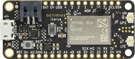
Icarus IoT Dev Board (nRF9160 Feather)
The Icarus is a cost-effective cellular IoT board in Adafruit’s Feather/FeatherWing form factor. It is built around Nordic Semi’s nRF9160 modem and combines LTE-M, NB-IoT, GPS, accelerometer, USB, LiPo charger as well as an eSIM and a nano SIM connector.
The main uController is the Nordic Semiconductor nRF9160, with ARM Cortex-M33F CPU, ARMv8-M Security Extension and the following devices (provided directly by Nordic):
ADC
CLOCK
FLASH
GPIO
I2C
MPU
NVIC
PWM
RTC
Segger RTT (RTT Console)
SPI
UARTE
WDT
IDAU
Hardware
The detailed information about the on-board hardware can be found at the Icarus Product Website [2].
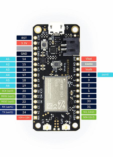
Icarus IoT Dev Board w/ Pinouts
Pin description
External Pins available to user:
Icarus pin |
Function |
Description |
Device-tree node |
|---|---|---|---|
RST |
Reset |
Active low reset with internal pullup |
|
3.3V |
Power output |
Main 3.3 V supply |
|
NC |
Not connected |
||
GND |
Power output |
Ground |
|
14 / A1 |
GPIO / Analog in |
nRF9160 P0.14 / AIN1 |
gpio0 / adc_1 |
15 / A2 |
GPIO / Analog in |
nRF9160 P0.15 / AIN2 |
gpio0 / adc_2 |
16 / A3 |
GPIO / Analog in |
nRF9160 P0.16 / AIN3 |
gpio0 / adc_3 |
17 / A4 |
GPIO / Analog in |
nRF9160 P0.17 / AIN4 |
gpio0 / adc_4 |
18 / A5 |
GPIO / Analog in |
nRF9160 P0.18 / AIN5 |
gpio0 / adc_5 |
19 / A6 |
GPIO / Analog in |
nRF9160 P0.19 / AIN6 |
gpio0 / adc_6 |
20 / SCK |
GPIO / SPI pin |
nRF9160 P0.20 / SPI SCK pin |
gpio0 / spi3 |
21 / MOSI |
GPIO / SPI pin |
nRF9160 P0.21 / SPI MOSI pin |
gpio0 / spi3 |
22 / MISO |
GPIO / SPI pin |
nRF9160 P0.22 / SPI MISO pin |
gpio0 / spi3 |
23 / RX |
GPIO / UART pin |
nRF9160 P0.23 / UART RX pin |
gpio0 / uart1 |
24 / TX |
GPIO / UART pin |
nRF9160 P0.24 / UART TX pin |
gpio0 / uart1 |
VIN |
Power input |
Voltage input (maximum 10.2 V) |
|
VBAT |
Power input |
Battery voltage input |
|
EN |
Power enable |
Power enable pin (pull low to disable power) |
|
USB |
Power input |
USB voltage input |
gpio0 |
4 |
GPIO |
nRF9160 P0.04 |
gpio0 |
3 |
GPIO |
nRF9160 P0.03 |
gpio0 |
2 |
GPIO |
nRF9160 P0.02 |
gpio0 |
1 |
GPIO |
nRF9160 P0.01 |
gpio0 |
0 |
GPIO |
nRF9160 P0.00 |
gpio0 |
30 |
GPIO |
nRF9160 P0.30 |
gpio0 |
31 |
GPIO |
nRF9160 P0.31 |
gpio0 |
SCL |
GPIO / I2C pin |
nRF9160 P0.26 / I2C SCL pin |
gpio0 / i2c2 |
SDA |
GPIO / I2C pin |
nRF9160 P0.27 / I2C SDA pin |
gpio0 / i2c2 |
nRF9160 pins connected internally:
nRF9160 pin |
Function |
Device-tree node |
|---|---|---|
P0.05 |
User button |
button0 |
P0.10 |
Red LED |
led0 / pwm-led0 |
P0.11 |
Green LED |
led1 / pwm-led1 |
P0.12 |
Blue LED |
led2 / pwm-led2 |
P0.28 |
Accelerometer Interrupt 1 |
lis2dh12-accel |
P0.29 |
Accelerometer Interrupt 2 |
lis2dh12-accel |
P0.08 |
SIM select pin |
gpio0 |
P0.13 / AIN0 |
Battery voltage measurement |
adc_0 |
P0.06 |
USB - FTDI serial RX |
uart0 |
P0.09 |
USB - FTDI serial TX |
uart0 |
P0.07 |
USB - FTDI serial RTS Charger enable pin (Icarus v2.0) |
uart0 gpio0 (Icarus v2.0) |
P0.25 |
USB - FTDI serial CTS FLASH memory SPI CS pin (Icarus v2.0) |
uart0 gpio0 (Icarus v2.0) |
Supported Features
The actinius_icarus board configuration supports the following hardware features:
Interface |
Controller |
Driver/Component |
|---|---|---|
ADC |
on-chip |
adc |
CLOCK |
on-chip |
clock_control |
FLASH |
on-chip |
flash |
GPIO |
on-chip |
gpio |
I2C(M) |
on-chip |
i2c |
MPU |
on-chip |
arch/arm |
NVIC |
on-chip |
arch/arm |
PWM |
on-chip |
pwm |
SPI(M/S) |
on-chip |
spi |
SPU |
on-chip |
system protection |
UARTE |
on-chip |
serial |
ACCEL |
st |
lis2dh |
SIM Selection
The SIM choice (eSIM or nano-SIM) can be configured in Devicetree by adjusting
the sim property in the sim_select node.
Charger Enable/Disable
Since hardware version 2.0 the charger can be disabled by adjusting the charger
property of the charger_enable device tree node.
Security components
Building Secure/Non-Secure Zephyr applications
The process requires the following steps:
Build the Secure Zephyr application using
-DBOARD=actinius_icarusandCONFIG_TRUSTED_EXECUTION_SECURE=yin the application project configuration file.Build the Non-Secure Zephyr application using
-DBOARD=actinius_icarus_ns.Merge the two binaries together.
If you are using Segger Embedded Studio v4.18 or later, the two binaries are built, merged, and burned automatically, unless you have disabled the feature.
When building a Secure/Non-Secure application, the Secure application will have to set the IDAU (SPU) configuration to allow Non-Secure access to all CPU resources utilized by the Non-Secure application firmware. SPU configuration shall take place before jumping to the Non-Secure application.
More information can be found in the Icarus “Get Started” Guide [3] or the Actinius Documentation Portal [4].