GigaDevice GD32F450I-EVAL
Overview
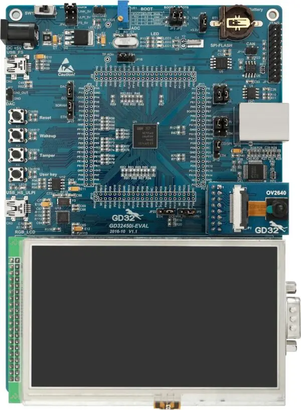
The GD32F450I-EVAL board is a hardware platform that enables prototyping on GD32F450IK Cortex-M4F Stretch Performance MCU.
The GD32F450IK features a single-core ARM Cortex-M4F MCU which can run up to 200 MHz with flash accesses zero wait states, 3072kiB of Flash, 256kiB of SRAM and 140 GPIOs.
Hardware
GD32F450IKT6 MCU
AT24C02C 2Kb EEPROM
GD25Q32C 16Mbit SPI and QSPI NOR Flash
GD9FS1G8F2A 1Gbit NAND Flash
Micron MT48LC16M16A2P-6AIT 256Mbit SDRAM
3 x User LEDs
3 x User Push buttons
1 x USART (RS-232 at J1 connector)
1 x POT connected to an ADC input
Headphone interface
Micro SD Card Interface
USB FS connector
USB HS connector
1 x CAN
Ethernet Interface
3.5” RGB-LCD (320x480)
OV2640 Digital Camera
GD-Link on board programmer
J-Link/JTAG connector
For more information about the GD32F450 SoC and GD32F450I-EVAL board:
Supported Features
The board configuration supports the following hardware features:
Peripheral |
Kconfig option |
Devicetree compatible |
|---|---|---|
EXTI |
||
GPIO |
||
NVIC |
N/A |
|
PWM |
||
SYSTICK |
N/A |
N/A |
USART |
||
DAC |
||
I2C |
||
EEPROM |
||
ADC |
Serial Port
The GD32F450I-EVAL board has one serial communication port. The default port is USART0 with TX connected at PA9 and RX at PA10.
Programming and Debugging
Before programming your board make sure to configure boot and serial jumpers as follows:
J2/3: Select 2-3 for both (boot from user memory)
J5: Select 1-2 position (labeled as
USART0)
Using GD-Link
The GD32F450I-EVAL includes an onboard programmer/debugger (GD-Link) which allows flash programming and debugging over USB. There is also a JTAG header (J1) which can be used with tools like Segger J-Link.
Build the Zephyr kernel and the Hello World sample application:
west build -b gd32f450i_eval samples/hello_world
Run your favorite terminal program to listen for output. On Linux the terminal should be something like
/dev/ttyUSB0. For example:minicom -D /dev/ttyUSB0 -oThe -o option tells minicom not to send the modem initialization string. Connection should be configured as follows:
Speed: 115200
Data: 8 bits
Parity: None
Stop bits: 1
To flash an image:
west build -b gd32f450i_eval samples/hello_world
west flash
You should see “Hello World! gd32f450i_eval” in your terminal.
To debug an image:
west build -b gd32f450i_eval samples/hello_world
west debug