ST STM32F411E Discovery
Overview
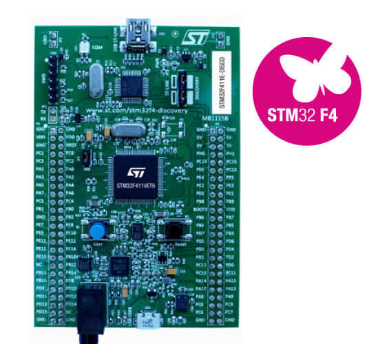
The STM32F411E Discovery kit features an ARM Cortex-M4 based STM32F411VE MCU with a wide range of connectivity support and configurations. Here are some highlights of the STM32F411E-DISCO board:
STM32F411VET6 microcontroller featuring 512 KB of Flash memory, 128 KB of RAM in an LQFP100 package
On-board ST-LINK/V2 with selection mode switch to use the kit as a standalone STLINK/V2 (with SWD connector for programming and debugging)
Board power supply: through USB bus or from an external 5 V supply voltage
External application power supply: 3 V and 5 V
L3GD20(rev B) or I3G4250D(rev D): ST MEMS motion sensor, 3-axis digital output gyroscope.
LSM303DLHC(rev B) or LSM303AGR(rev D): ST MEMS system-in-package featuring a 3D digital linear acceleration sensor and a 3D digital magnetic sensor.
MP45DT02(rev B) or IMP34DT05(rev D), ST MEMS audio sensor, omnidirectional digital microphone
CS43L22, audio DAC with integrated class D speaker driver
- Eight LEDs:
LD1 (red/green) for USB communication
LD2 (red) for 3.3 V power on
- Four user LEDs:
LD3 (orange), LD4 (green), LD5 (red) and LD6 (blue)
- Two USB OTG LEDs:
LD7 (green) VBus and LD8 (red) over-current
Two pushbuttons (user and reset)
USB OTG with micro-AB connector
Extension header for LQFP100 I/Os for a quick connection to the prototyping board and an easy probing
More information about the board can be found at the 32F411EDISCOVERY website [1].
Hardware
STM32F411E-DISCO Discovery kit provides the following hardware components:
STM32F411VET6 in LQFP100 package
ARM® 32-bit Cortex® -M4 CPU with FPU
100 MHz max CPU frequency
VDD from 1.7 V to 3.6 V
512 KB Flash
128 KB SRAM
GPIO with external interrupt capability
1x12-bit, 2.4 MSPS ADC with 16 channels
DMA Controller
Up to 11 Timers (six 16-bit, two 32-bit, two watchdog timers and a SysTick timer)
USART/UART (3)
I2C (3)
SPI/I2S (5)
SDIO
USB 2.0 full-speed device/host/OTG controller with on-chip PHY
CRC calculation unit
96-bit unique ID
RTC
- More information about STM32F411VE can be found here:
Supported Features
The Zephyr stm32f411e_disco board configuration supports the following hardware features:
Interface |
Controller |
Driver/Component |
|---|---|---|
NVIC |
on-chip |
nested vector interrupt controller |
UART |
on-chip |
serial port-polling; serial port-interrupt |
PINMUX |
on-chip |
pinmux |
GPIO |
on-chip |
gpio |
PWM |
on-chip |
pwm |
Other hardware features are not yet supported on Zephyr porting.
The default configuration can be found in the defconfig file boards/arm/stm32f411e_disco/stm32f411e_disco_defconfig
Pin Mapping
STM32F411E-DISCO Discovery kit has 5 GPIO controllers. These controllers are responsible for pin muxing, input/output, pull-up, etc.
For more details please refer to 32F411EDISCOVERY board User Manual [2].
Default Zephyr Peripheral Mapping:
UART_2_TX : PA2
UART_2_RX : PA3
LD3 : PD13 (PWM4 CH2)
LD4 : PD12 (PWM4 CH1)
LD5 : PD14 (PWM4 CH3)
LD6 : PD15 (PWM4 CH4)
System Clock
STM32F411E-DISCO System Clock could be driven by an internal or external oscillator, as well as the main PLL clock. By default, the System clock is driven by the PLL clock at 100MHz, driven by the internal oscillator.
Serial Port
The STM32F411G Discovery kit has up to 3 UARTs. The Zephyr console output is assigned to UART2. Default settings are 115200 8N1.
Programming and Debugging
Applications for the stm32f411e_disco board configuration can be built and
flashed in the usual way (see Building an Application and
Run an Application for more details).
Flashing
STM32F411E-DISCO Discovery kit includes an ST-LINK/V2 embedded debug tool interface. This interface is supported by the openocd version included in Zephyr SDK.
Flashing an application to STM32F411E-DISCO
Connect the STM32F411E-DISCO Discovery kit to your host computer using the USB port. Then build and flash an application.
Here is an example for the Blinky application.
# From the root of the zephyr repository
west build -b stm32f411e_disco samples/basic/blinky
west flash
In case you are using PCB revision B, you have to use an adapted board definition as the default PCB rev here is D:
# From the root of the zephyr repository
west build -b stm32f411e_disco@B samples/basic/blinky
west flash
You should see the orange led (LD3) blinking every second.
Debugging
You can debug applications in the usual way. Here is an example for the Blinky application.
# From the root of the zephyr repository
west build -b stm32f411e_disco samples/basic/blinky
west debug