EFR32 Radio Boards
Overview
Support for EFR32 Radio boards is provided by one of the starter kits
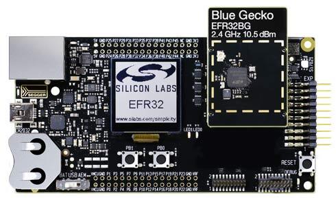
SLWSTK6020B (image courtesy of Silicon Labs)
Hardware
Wireless Starter Kit Mainboard:
Advanced Energy Monitoring provides real-time information about the energy consumption of an application or prototype design.
Ultra-low power 128x128 pixel memory LCD
2 user buttons and 2 LEDs
20 pin expansion header
Si7021 Humidity and Temperature Sensor
On-board Segger J-Link USB and Ethernet debugger
For more information about the BRD4001A board, refer to these documents:
Supported Features
The board configuration supports the following hardware features:
Interface |
Controller |
Driver/Component |
|---|---|---|
MPU |
on-chip |
memory protection unit |
NVIC |
on-chip |
nested vector interrupt controller |
SYSTICK |
on-chip |
systick |
COUNTER |
on-chip |
rtcc |
FLASH |
on-chip |
flash memory |
GPIO |
on-chip |
gpio |
UART |
on-chip |
serial port-polling; serial port-interrupt |
SPI(M) |
on-chip |
spi port-polling |
WATCHDOG |
on-chip |
watchdog |
Other hardware features are currently not supported by the port.
Connections and IOs
In the following table, the column Name contains Pin names. For example, PA2 means Pin number 2 on PORTA, as used in the board’s datasheets and manuals.
Name |
Function |
Usage |
|---|---|---|
PF4 |
GPIO |
LED0 |
PF5 |
GPIO |
LED1 |
PF6 |
GPIO |
Push Button PB0 |
PF7 |
GPIO |
Push Button PB1 |
PA5 |
GPIO |
Board Controller Enable EFM_BC_EN |
PA0 |
USART0_TX |
UART Console EFM_BC_TX US0_TX #0 |
PA1 |
USART0_RX |
UART Console EFM_BC_RX US0_RX #0 |
PC6 |
SPI_MOSI |
Flash MOSI US1_TX #11 |
PC7 |
SPI_MISO |
Flash MISO US1_RX #11 |
PC8 |
SPI_SCLK |
Flash SCLK US1_CLK #11 |
PA4 |
SPI_CS |
Flash Chip Select (GPIO) |
Programming and Debugging
The BRD4001A includes an J-Link serial and debug adaptor built into the board. The adaptor provides:
A USB connection to the host computer, which exposes a debug interface and a USB Serial Port.
A physical UART connection which is relayed over interface USB Serial port.
An Ethernet connection to support remote debugging.
It is compatible with the following host debug tools:
OpenOCD is included in the Zephyr SDK. Refer to the links above for information on how to install required host debug tools if you are not using the Zephyr SDK.
Flashing
Connect the BRD4001A main board with the mounted radio module to your host computer using the USB port.
Following example shows how to build the Hello World application for BRD4104A radio module.
# From the root of the zephyr repository
west build -b efr32_radio_brd4104a samples/hello_world
west flash
Open a serial terminal (minicom, putty, etc.) with the following settings:
Speed: 115200
Data: 8 bits
Parity: None
Stop bits: 1
Reset the board and you should see the following message in the terminal:
Hello World! efr32_radio_brd4104a