Wiznet W5500 Evaluation Pico
Overview
W5500-EVB-Pico is a microcontroller evaluation board based on the Raspberry Pi RP2040 and fully hardwired TCP/IP controller W5500 - and basically works the same as Raspberry Pi Pico board but with additional Ethernet via W5500. The USB bootloader allows the ability to flash without any adapter, in a drag-and-drop manner. It is also possible to flash and debug the boards with their SWD interface, using an external adapter.
Hardware
Dual core Arm Cortex-M0+ processor running up to 133MHz
264KB on-chip SRAM
16MB on-board QSPI flash with XIP capabilities
26 GPIO pins
3 Analog inputs
2 UART peripherals
2 SPI controllers
2 I2C controllers
16 PWM channels
USB 1.1 controller (host/device)
8 Programmable I/O (PIO) for custom peripherals
On-board LED
1 Watchdog timer peripheral
Wiznet W5500 Ethernet MAC/PHY
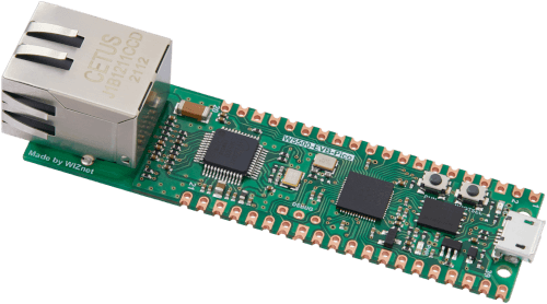
Wiznet W5500_EVB_PICO evaluation board (Image courtesy of Wiznet)
Supported Features
The w5500_evb_pico board configuration supports the following hardware features:
Peripheral |
Kconfig option |
Devicetree compatible |
|---|---|---|
NVIC |
N/A |
|
UART |
||
GPIO |
||
ADC |
||
I2C |
||
SPI |
||
USB Device |
||
HWINFO |
N/A |
|
Watchdog Timer (WDT) |
||
PWM |
||
Flash |
|
|
UART (PIO) |
||
SPI (PIO) |
||
W5500 Ethernet |
Pin Mapping
The peripherals of the RP2040 SoC can be routed to various pins on the board. The configuration of these routes can be modified through DTS. Please refer to the datasheet to see the possible routings for each peripheral.
External pin mapping on the W5500_EVB_PICO is identical to the Raspberry Pi Pico. Since GPIO 25 is routed to the on-board LED on, similar to the Raspberry Pi Pico, the blinky example works as intended. The W5500 is routed to the SPI0 (P16-P19), with the reset and interrupt signal for the W5500 routed to P20 and P21, respectively. All of these are shared with the edge connector on the board.
Refer to W55500 Evaluation Board Documentation [3] for a board schematic and other certifications.
Default Zephyr Peripheral Mapping:
UART0_TX : P0
UART0_RX : P1
I2C0_SDA : P4
I2C0_SCL : P5
I2C1_SDA : P14
I2C1_SCL : P15
SPI0_RX : P16
SPI0_CSN : P17
SPI0_SCK : P18
SPI0_TX : P19
W5500 Reset : P20
W5500 Interrupt : P21
ADC_CH0 : P26
ADC_CH1 : P27
ADC_CH2 : P28
ADC_CH3 : P29
Programming and Debugging
Flashing
Using SEGGER JLink
You can Flash the w5500_evb_pico with a SEGGER JLink debug probe as described in Building, Flashing and Debugging.
Here is an example of building and flashing the Blinky application.
# From the root of the zephyr repository
west build -b w5500_evb_pico samples/basic/blinky
west flash --runner jlink
Using OpenOCD
To use PicoProbe, You must configure udev.
Create a file in /etc/udev.rules.d with any name, and write the line below.
ATTRS{idVendor}=="2e8a", ATTRS{idProduct}=="000c", MODE="660", GROUP="plugdev", TAG+="uaccess"
This example is valid for the case that the user joins to plugdev groups.
The Raspberry Pi Pico, and thus the W55500 Evaluation Board, has an SWD interface that can be used to program and debug the on board RP2040. This interface can be utilized by OpenOCD. To use it with the RP2040, OpenOCD version 0.12.0 or later is needed.
If you are using a Debian based system (including RaspberryPi OS, Ubuntu. and more), using the pico_setup.sh [1] script is a convenient way to set up the forked version of OpenOCD.
Depending on the interface used (such as JLink), you might need to checkout to a branch that supports this interface, before proceeding. Build and install OpenOCD as described in the README.
Here is an example of building and flashing the Blinky application.
# From the root of the zephyr repository
west build -b w5500_evb_pico samples/basic/blinky -- -DOPENOCD=/usr/local/bin/openocd -DOPENOCD_DEFAULT_PATH=/usr/local/share/openocd/scripts -DRPI_PICO_DEBUG_ADAPTER=picoprobe
west flash
Set the environment variables OPENOCD to /usr/local/bin/openocd and OPENOCD_DEFAULT_PATH to /usr/local/share/openocd/scripts. This should work with the OpenOCD that was installed with the default configuration. This configuration also works with an environment that is set up by the pico_setup.sh [1] script.
RPI_PICO_DEBUG_ADAPTER specifies what debug adapter is used for debugging.
If RPI_PICO_DEBUG_ADAPTER was not assigned, picoprobe is used by default. The other supported adapters are raspberrypi-swd, jlink and blackmagicprobe. How to connect picoprobe and raspberrypi-swd is described in Getting Started with Raspberry Pi Pico [2]. Any other SWD debug adapter maybe also work with this configuration.
The value of RPI_PICO_DEBUG_ADAPTER is cached, so it can be omitted from west flash and west debug if it was previously set while running west build.
RPI_PICO_DEBUG_ADAPTER is used in an argument to OpenOCD as “source [find interface/${RPI_PICO_DEBUG_ADAPTER}.cfg]”. Thus, RPI_PICO_DEBUG_ADAPTER needs to be assigned the file name of the debug adapter.
You can also flash the board with the following command that directly calls OpenOCD (assuming a SEGGER JLink adapter is used):
$ openocd -f interface/jlink.cfg -c 'transport select swd' -f target/rp2040.cfg -c "adapter speed 2000" -c 'targets rp2040.core0' -c 'program path/to/zephyr.elf verify reset exit'
Using UF2
If you don’t have an SWD adapter, you can flash the Raspberry Pi Pico with a UF2 file. By default, building an app for this board will generate a build/zephyr/zephyr.uf2 file. If the Pico is powered on with the BOOTSEL button pressed, it will appear on the host as a mass storage device. The UF2 file should be drag-and-dropped to the device, which will flash the Pico.
Debugging
The SWD interface can also be used to debug the board. To achieve this, you can either use SEGGER JLink or OpenOCD.
Using SEGGER JLink
Use a SEGGER JLink debug probe and follow the instruction in Building, Flashing and Debugging.
Using OpenOCD
Install OpenOCD as described for flashing the board.
Here is an example for debugging the Blinky application.
# From the root of the zephyr repository
west build -b w5500_evb_pico samples/basic/blinky -- -DOPENOCD=/usr/local/bin/openocd -DOPENOCD_DEFAULT_PATH=/usr/local/share/openocd/scripts -DRPI_PICO_DEBUG_ADAPTER=raspberrypi-swd
west debug
As with flashing, you can specify the debug adapter by specifying RPI_PICO_DEBUG_ADAPTER at west build time. No needs to specify it at west debug time.
You can also debug with OpenOCD and gdb launching from command-line. Run the following command:
$ openocd -f interface/jlink.cfg -c 'transport select swd' -f target/rp2040.cfg -c "adapter speed 2000" -c 'targets rp2040.core0'
On another terminal, run:
$ gdb-multiarch
Inside gdb, run:
(gdb) tar ext :3333
(gdb) file path/to/zephyr.elf
You can then start debugging the board.