EFM32GG12 Thunderboard Kit
Overview
The EFM32GG12 Thunderboard Kit (SLTB009A) is an evaluation platform for the EFM32GG12 GiantGecko Microcontroller, featuring an ARM Cortex-M4 with FPU, 1024kB flash, and 192kB RAM.
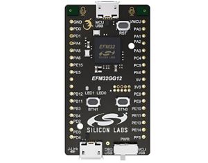
SLTB009A (Credit: Silicon Labs)
Hardware
PDM stereo microphones
USB connectivity
On-board Segger J-Link USB debugger
2 user buttons and 2 LEDs
USB C connector
For more information about the WGM160P and SLTB009A board:
Supported Features
The efm32gg_sltb009a board configuration supports the following hardware features:
Interface |
Controller |
Driver/Component |
|---|---|---|
MPU |
on-chip |
memory protection unit |
COUNTER |
on-chip |
rtcc |
FLASH |
on-chip |
flash memory |
GPIO |
on-chip |
gpio |
I2C |
on-chip |
i2c port-polling |
NVIC |
on-chip |
nested vector interrupt controller |
UART |
on-chip |
serial port-polling; serial port-interrupt |
The default configuration can be found in the defconfig file:
boards/arm/efm32gg_sltb009a/efm32gg_sltb009a_defconfig
Connections and IOs
The EFM32GG12 MCU has six GPIO controllers (PORTA to PORTF), all of which are currently enabled for the SLTB009A board.
In the following table, the column Name contains pin names. For example, PE1 means pin number 1 on PORTE, as used in the board’s datasheets and manuals.
Name |
Function |
Usage |
|---|---|---|
PE12 |
GPIO |
LED0 |
PA13 |
GPIO |
LED1 |
PD5 |
GPIO |
Push Button PB0 |
PD8 |
GPIO |
Push Button PB1 |
PE7 |
UART_TX |
UART TX Console VCOM_TX US0_TX #1 |
PE6 |
UART_RX |
UART RX Console VCOM_RX US0_RX #1 |
PC0 |
I2C_SDA |
SENSOR_I2C_SDA I2C0_SDA #1 |
PC1 |
I2C_SCL |
SENSOR_I2C_SCL I2C0_SCL #1 |
PC4 |
I2C_SDA |
SENSOR_I2C_SDA I2C1_SDA #1 |
PC5 |
I2C_SCL |
SENSOR_I2C_SCL I2C1_SCL #1 |
System Clock
The EFM32GG12 MCU is configured to work at 72 MHz.
Serial Port
The EFM32GG12 SoC has five USARTs, two UARTs and two Low Energy UARTs (LEUART). USART0 is connected to the board controller and is used for the console.
Programming and Debugging
Note
Before using the kit the first time, you should update the J-Link firmware from J-Link-Downloads
Flashing
The SLTB009A includes an J-Link serial and debug adaptor built into the board. The adaptor provides:
A USB connection to the host computer
A physical UART connection which is relayed over interface USB serial port.
Flashing an application to SLTB009A
Connect the SLTB009A to your host computer using the USB port.
Here is an example to build and flash the Hello World application.
# From the root of the zephyr repository
west build -b efm32gg_stb009a samples/hello_world
west flash
Open a serial terminal (minicom, putty, etc.) with the following settings:
Speed: 115200
Data: 8 bits
Parity: None
Stop bits: 1
Reset the board and you’ll see the following message on the corresponding serial port terminal session:
Hello World! efm32gg_sltb009a