NXP UCANS32K1SIC
Overview
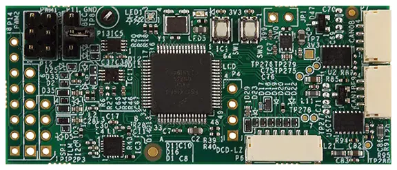
NXP UCANS32K1SIC [1] is a CAN signal improvement capability (SIC) evaluation board designed for both automotive and industrial applications. The UCANS32K1SIC provides two CAN SIC interfaces and is based on the 32-bit Arm Cortex-M4F NXP S32K146 [2] microcontroller.
Hardware
- NXP S32K146
Arm Cortex-M4F @ up to 112 Mhz
1 MB Flash
128 KB SRAM
up to 127 I/Os
3x FlexCAN with 2x FD
eDMA, 12-bit ADC, MPU, ECC and more.
- Interfaces:
DCD-LZ debug interface with SWD + Console / UART
Dual CAN FD PHYs with dual connectors for daisy chain operation
JST-GH DroneCode compliant standard connectors and I/O headers
user RGB LED and button.
More information about the hardware and design resources can be found at NXP UCANS32K1SIC [1] website.
Supported Features
The ucans32k1sic board configuration supports the following hardware features:
Interface |
Controller |
Driver/Component |
|---|---|---|
SYSMPU |
on-chip |
mpu |
PORT |
on-chip |
pinctrl |
GPIO |
on-chip |
gpio |
LPUART |
on-chip |
serial |
LPI2C |
on-chip |
i2c |
LPSPI |
on-chip |
spi |
FTM |
on-chip |
pwm |
FlexCAN |
on-chip |
can |
Watchdog |
on-chip |
watchdog |
RTC |
on-chip |
counter |
The default configuration can be found in the Kconfig file boards/arm/ucans32k1sic/ucans32k1sic_defconfig.
Connections and IOs
This board has 5 GPIO ports named from gpioa to gpioe.
Pin control can be further configured from your application overlay by adding
children nodes with the desired pinmux configuration to the singleton node
pinctrl. Supported properties are described in
dts/bindings/pinctrl/nxp,kinetis-pinctrl.yaml.
LEDs
The UCANS32K1SIC board has one user RGB LED that can be used either as a GPIO LED or as a PWM LED.
Devicetree node |
Devicetree alias |
Label |
Pin |
|---|---|---|---|
led1_red |
led0 |
LED1_RGB_RED |
PTD15 |
led1_green |
led1 |
LED1_RGB_GREEN |
PTD16 |
led1_blue |
led2 |
LED1_RGB_BLUE |
PTD0 |
Devicetree node |
Devicetree alias |
Label |
Pin |
|---|---|---|---|
led1_red_pwm |
pwm-led0 / red-pwm-led |
LED1_RGB_RED_PWM |
PTD15 / FTM0_CH0 |
led1_green_pwm |
pwm-led1 / green-pwm-led |
LED1_RGB_GREEN_PWM |
PTD16 / FTM0_CH1 |
led1_blue_pwm |
pwm-led2 / blue-pwm-led |
LED1_RGB_BLUE_PWM |
PTD0 / FTM0_CH2 |
The user can control the LEDs in any way. An output of 0 illuminates the LED.
Serial Console
The serial console is provided via lpuart1 on the 7-pin DCD-LZ debug
connector P6.
Connector |
Pin |
Pin Function |
|---|---|---|
P6.2 |
PTC7 |
LPUART1_TX |
P6.3 |
PTC6 |
LPUART1_RX |
System Clock
The Arm Cortex-M4F core is configured to run at 80 MHz (RUN mode).
Programming and Debugging
Applications for the ucans32k1sic board can be built in the usual way as
documented in Building an Application.
This board configuration supports Lauterbach TRACE32 [3] and SEGGER J-Link [4] West runners for flashing and debugging applications. Follow the steps described in Lauterbach TRACE32 Debug Host Tools and J-Link Debug Host Tools, to setup the flash and debug host tools for these runners, respectively. The default runner is J-Link.
Flashing
Run the west flash command to flash the application using SEGGER J-Link.
Alternatively, run west flash -r trace32 to use Lauterbach TRACE32.
The Lauterbach TRACE32 runner supports additional options that can be passed through command line:
west flash -r trace32 --startup-args elfFile=<elf_path> loadTo=<flash/sram>
   eraseFlash=<yes/no> verifyFlash=<yes/no>
Where:
<elf_path>is the path to the Zephyr application ELF in the output directoryloadTo=flashloads the application to the SoC internal program flash (CONFIG_XIPmust be set), andloadTo=sramload the application to SRAM. The default isflash.eraseFlash=yeserases the whole content of SoC internal flash before the application is downloaded to either Flash or SRAM. This routine takes time to execute. The default isno.verifyFlash=yesverify the SoC internal flash content after programming (use together withloadTo=flash). The default isno.
For example, to erase and verify flash content:
west flash -r trace32 --startup-args elfFile=build/zephyr/zephyr.elf loadTo=flash eraseFlash=yes verifyFlash=yes
Debugging
Run the west debug command to start a GDB session using SEGGER J-Link.
Alternatively, run west debug -r trace32 to launch the Lauterbach TRACE32
software debugging interface.